Contact element for shielded connectors

a shielding connector and contact element technology, applied in the direction of coupling contact members, coupling device connections, coupling/disengagement of coupling parts, etc., can solve the problem of requiring additional components, and achieve the effect of convenient connection of shielding

Active Publication Date: 2010-01-26
HARTING ELECTRIC GMBH & CO KG
View PDF10 Cites 38 Cited by
  • Summary
  • Abstract
  • Description
  • Claims
  • Application Information

AI Technical Summary

Benefits of technology

[0009]The invention is based on the objective of realizing the contacting for a connector in such a way that the user is able to easily connect the shielding to the connector, wherein the contact element is connected to the connector in a captive fashion.
[0012]This is the reason why an exchangeable variation of a splicing ring was developed for a connector system with circular connectors that has been produced for quite some time, wherein this variation of a splicing ring makes it possible to easily lay the shielding of an electric cable on such a connector.
[0014]The wall segment is shaped about semicircularly in accordance with the sleeve-shaped cable guide part and provided with a toggle lever that can be inserted into the interior of the cable guide part and engages therein, but advantageously allows an outward tilting movement. In this case, it is also advantageous that the wall segment that can be disengaged forms a funnel-shaped passage for simplifying the insertion of an electric cable.

Problems solved by technology

In this case, it is disadvantageous that an additional component is required in most instances in order to realize the electric contacting, wherein this additional component is supplied separately, easily forgotten during the assembly or lost.

Method used


Image

  • Contact element for shielded connectors
  • Contact element for shielded connectors
  • Contact element for shielded connectors

Examples


Embodiment Construction

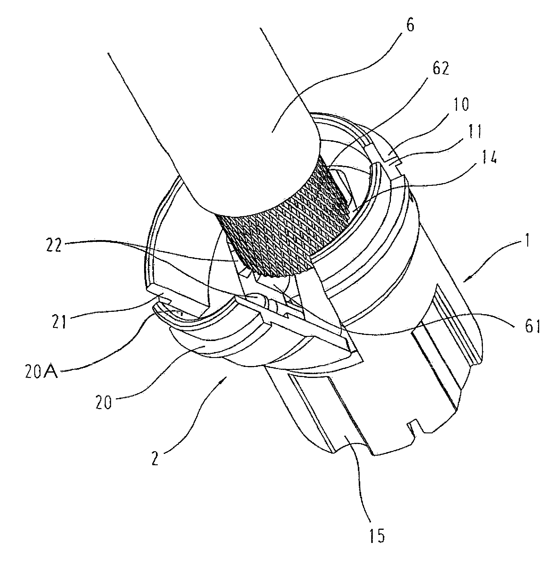
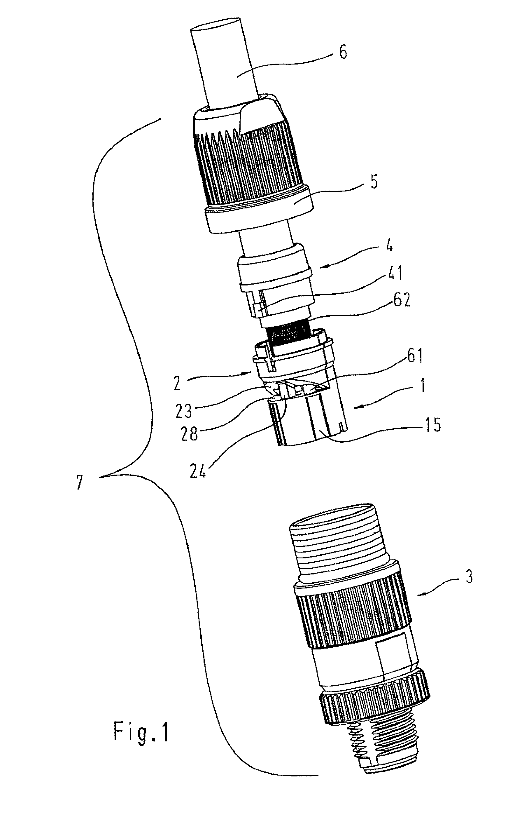
[0024]FIG. 1 shows a connector 7 in the form of a partially exploded representation with an electric cable 6, a coupling ring 5 that is pushed on said cable, a sealing insert 4 and a cable guide part 1 that is also referred to as a splicing ring, as well as a plug contact insert 3, in which not-shown electric contacts are arranged.

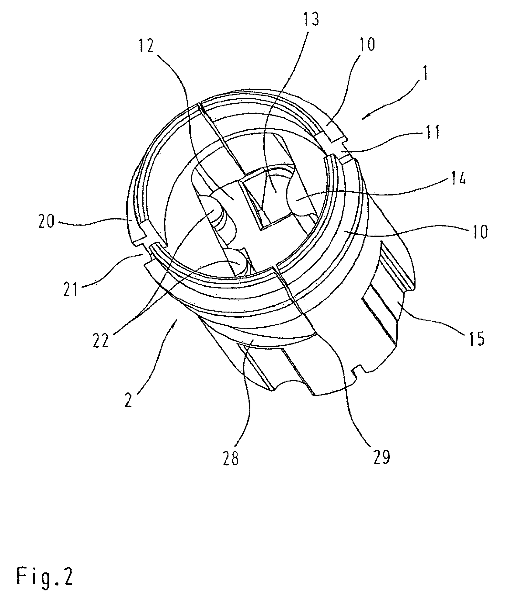
[0025]The cable guide part 1 features several specially shaped through-openings 13 in its interior, wherein one individual electric conductor contacted by an electric contact needs to be respectively inserted into said through-openings.

[0026]A contact element realized in the form of a wall segment 2 is also assigned to the cable guide part 1, wherein said wall segment occupies a recessed semicircle 20A of the cable guide part and can be tilted radially outward about an acutely angled edge 29 within the angular range of the recessed section of the cable guide part.

[0027]A zone 28 with a wedge angle of 30° formed by the acutely angled edge 29 is required in ...


PUM


Abstract

To connect the shielding of an electric cable to a metallic connector, an electrically non-conductive cable guide part that features a wall segment of an electrically conductive material that needs to be laterally opened sectionally is provided. In this case, the shielding of the electric cable lying in the interior is connected to a corresponding mating connector by means of the wall segment and an electrically conductive connector sleeve surrounding the connector.

Description

BACKGROUND OF THE INVENTION[0001]1. Field of the Invention[0002]The invention pertains to a contact element for connecting the shielding of an electric cable to a connector.[0003]A contact element of this type is required for easily contacting the shielding of a shielded cable with a connector to be shielded against electric interference signals.[0004]2. Description of the Related Art[0005]The braided shielding of an electric cable or conductor can be contacted with a connector housing to be shielded with a variety of known connectors.[0006]Different mechanical devices have been proposed in this respect, wherein DE 41 37 355 C2 discloses an electric connector for shielded cables, in which an electrically conductive elastomer part is provided for the electric connection between the shielding of the cable and the housing.[0007]DE 90 15 056 U1 discloses a circular electric connector that is impervious to water and high frequencies, wherein the shielding of the cable lies on an electric...

Claims


Application Information

Patent Timeline
Patent Type & Authority Patents(United States)
IPC IPC(8): H01R9/03
CPCH01R9/032H01R9/0524H01R13/506H01R13/65912
Inventor SCHREIER, STEPHAN
Owner HARTING ELECTRIC GMBH & CO KG
Why Eureka
Try Eureka