
Clock synchronization and distribution over a legacy optical Ethernet network

a legacy optical ethernet network and clock synchronization technology, applied in the field of data communication, can solve the problems of inability to convey information synchronously, conventional ethernet networks lack clock synchronization mechanisms, and a large amount of fiber installed in both new and existing facilities

Inactive Publication Date: 2010-01-19
NOKIA SIEMENS NETWORKS ETHERNET SOLUTIONS +1
View PDF5 Cites 54 Cited by
  • Summary
  • Abstract
  • Description
  • Claims
  • Application Information

AI Technical Summary

Benefits of technology

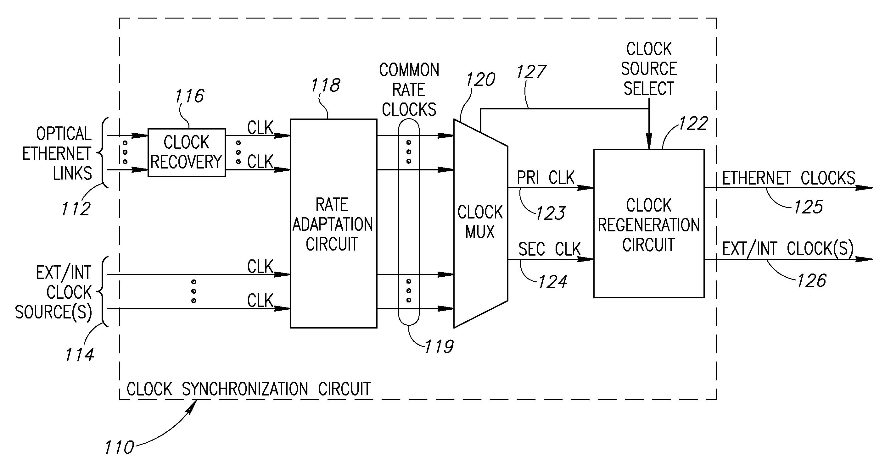
[0030]There is therefore provided in accordance with the invention, an Ethernet clock synchronization device for enabling legacy Ethernet devices to participate in a clock synchronous optical Ethernet network comprising a plurality of Ethernet PHY receive circuits coupled to one or more legacy Ethernet devices and to one or more neighboring nodes, the receive circuits operative to receive synchronous and asynchronous optical Ethernet signals and to recover clock signals therefrom, a rate adaptation circuit operative to translate the rate of each recovered clock signal to a common rate to yield a plurality of common rate adapted clock signals, clock selection means for selecting one of the common rate adapted clock signals as a primary clock signal, conversion means for generating one or more synchronous Ethernet clock signals derived from the primary clock signal and a plurality of Ethernet PHY transmit circuits coupled to the one or more legacy Ethernet devices and to the one or more neighboring nodes the transmit circuits operative to generate transmit optical Ethernet signals utilizing the one or more synchronous Ethernet clock signals.
[0031]There is also provided in accordance with the invention, a method of clock synchronization and distribution for enabling legacy Ethernet devices to participate in a clock synchronous optical Ethernet network, the method comprising the steps of receiving synchronous and asynchronous input optica

Problems solved by technology

In response, there has been a massive explosion in the amount of fiber being installed into both new and existing facilities.
A problem arises from the fact that conventional Ethernet networks are designed to transfer packets from one location to another asynchronously.
Conventional Ethernet networks lack a mechanism for providing clock synchronization and distribution from a centralized clock source location.
They are not capable of conveying information synchronously and thus cannot support TDM traffic streams, for example.
10 Gigabit LAN Ethernet, however, does not explicitly provide any interoperability at the bitstream level with other SONET / SDH systems.
A disadvantage of using a SONET / SDH network for clock synchronization is the high cost of such networks.
A further disadvantage is that having been developed for TDM networks, SONET / SDH networks are not optimized for Ethernet transport which transmits data asynchronously.
Thus, a problem exists in how to transfer legacy TDM traffic over an asynchronous Ethernet network and particularly, how to extract and reconstruct the TDM clock from the received data at the other side.
This approach, however, does not address transporting TDM traffic over asynchronous Ethernet networks.
A disadvantage of this scheme, however, is that the jitter and wonder generated is relatively high and typically does not meet common carrier telecommunication standards.
In addition, the scheme cannot track the master clock in the event a large number of packets are lost and is overly sensitive to lost and erroneous packets.
The clock quality output from this mechanism is, however, of medium quality.
In addition, it is susceptible to network delays and congestion.

Method used


Image

  • Clock synchronization and distribution over a legacy optical Ethernet network
  • Clock synchronization and distribution over a legacy optical Ethernet network
  • Clock synchronization and distribution over a legacy optical Ethernet network

Examples


embodiment

Provider Switch Embodiment

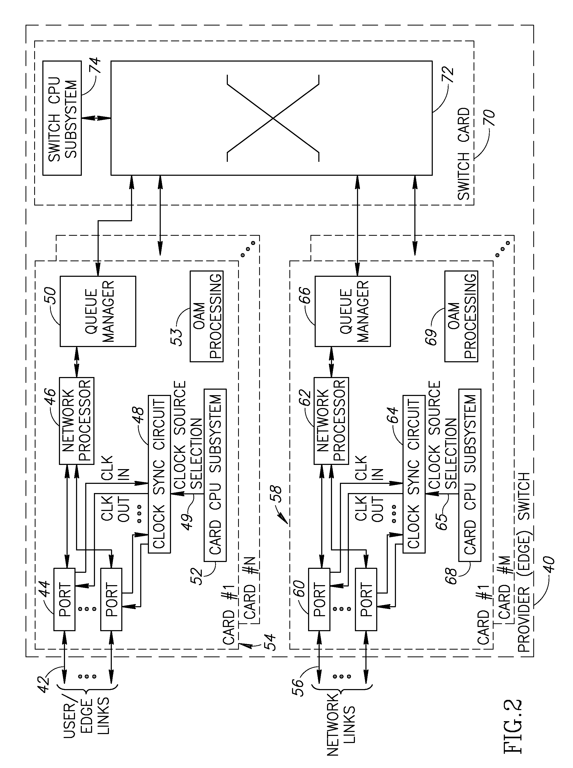
[0059]A network device can be adapted to incorporate the clock synchronization mechanism of the present invention. Hardware means and / or software means adapted to execute the mechanism may be incorporated, for example, within the line cards of a network device such as a core switch, access switch, provider switch, enterprise switch, Network Management System (NMS), Label Switching Router (LSR), Ethernet LAN switch, network switch or any other wired or wireless network device. The network device may be constructed using any combination of hardware and / or software. A provider switch is defined as any switch used by a service provider. Examples of provider switches include edge switches, core switches and access switches. An enterprise switch is defined as any switch used within an enterprise, such as the switches used within a corporation, college campus, etc.

[0060]As an example, the invention is applied to a provider edge switch and a provider (core or middl...


PUM


Abstract

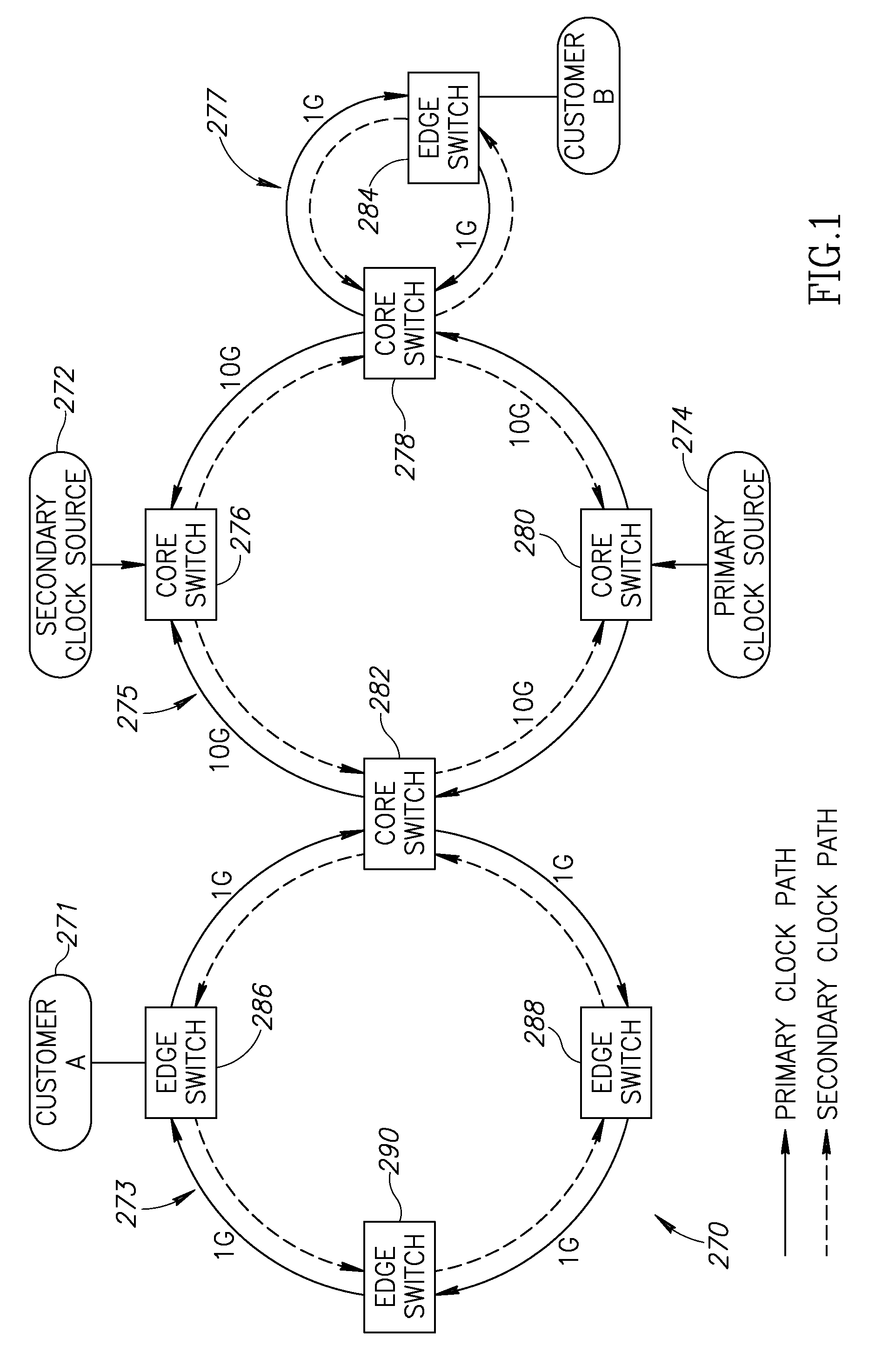
A novel clock method and synchronization mechanism for recovering and distributing a centralized clock source synchronously over legacy asynchronous network devices such as legacy optical Ethernet devices that do not support synchronous Ethernet. An external device functions transparently to provide legacy optical Ethernet devices a clock synchronization and distribution mechanism. The external devices implement a clock conversion scheme whereby multiple clocks having diverse rates are converted to clock signals all having a common rate. One of the converted clocks is selected and all downstream clock signals are then derived from this clock. A high quality clock source located anywhere on the network is distributed throughout the network thus turning an asynchronous Ethernet network into a synchronous Ethernet network. Synchronous TDM data streams can then be easily transported over the Ethernet network.

Description

REFERENCE TO PRIORITY APPLICATION[0001]This application claims priority under 35 U.S.C. §119(e) to U.S. Provisional Application Ser. No. 60 / 807,307, filed Jul. 13, 2006, entitled “Clock Synchronization And Distribution Over A Legacy Optical Ethernet Network,” incorporated herein by reference in its entirety.FIELD OF THE INVENTION[0002]The present invention relates to the field of data communications and more particularly relates to a clock synchronization and distribution mechanism for use in networks comprising legacy asynchronous optical Ethernet devices.BACKGROUND OF THE INVENTION[0003]The growth in demand for telecommunication services is increasing at an ever-quickening pace. The majority of the demand is being driven by the explosion in the use of the Internet and a steady stream of new applications being introduced which further increase the demand for increased bandwidth. Currently, a large portion of the Internet traffic is still carried by circuit switched transport facili...

Claims


Application Information

Patent Timeline
IPC IPC(8): H04J3/06
CPCH04J3/0688H04J3/0697H04L12/422H04J3/0641
Inventor WECHSLER, YOAVSHMILOVICI, ZVI
Owner NOKIA SIEMENS NETWORKS ETHERNET SOLUTIONS
Learn More