
Method of manufacturing a band with a fastener

a technology of fastener and band, applied in the field of banding system, can solve the problems of not teaching a method and apparatus, no clip is attached to the measured band,

Active Publication Date: 2010-01-12
VERESCHAGIN LAWRENCE WAYNE
View PDF14 Cites 120 Cited by
  • Summary
  • Abstract
  • Description
  • Claims
  • Application Information

AI Technical Summary

Benefits of technology

"This patent describes a machine and method for making a band of desired length with fastening means at one end. The machine includes spindle means for maintaining a spool of metal band material, feeding means for feeding and ejecting a metal strip material, end determination means for determining the location of the end of the band material, fastener placement means for positioning the fastener means, band folding means for bending the band about the fastener means, compressing means for compressing the band to the fastening means, cutting means for cutting a desired length of band, and control means for controlling the manufacturing process. The invention also provides a device for manufacturing a band of a selected length with fastening means at one end thereof, a method of manufacturing a band of a selected length with a fastener at one end thereof, and a strap for wrapping around a conduit. The technical effects of this invention include faster and more efficient production of bands with fastening means at one end, improved band quality, and reduced labor costs."

Problems solved by technology

Eisenberg teaches a machine which nails a metal band to a box, but does not attach a clip to the band, and does not automatically measure and cut bands for later application to an object.
Chak does not teach a method and apparatus for attaching a clip to a band of a desired length.
In Helland, a desired length of band can be measured and cut, however, no clip is attachable to the measured band.

Method used


Image

  • Method of manufacturing a band with a fastener
  • Method of manufacturing a band with a fastener
  • Method of manufacturing a band with a fastener

Examples


Embodiment Construction

[0021]In the description which follows, like parts are marked throughout the specification and the drawings with the same respective reference numerals. The drawings are not necessarily to scale and in some instances proportions may have been exaggerated in order to more clearly depict certain features of the invention.

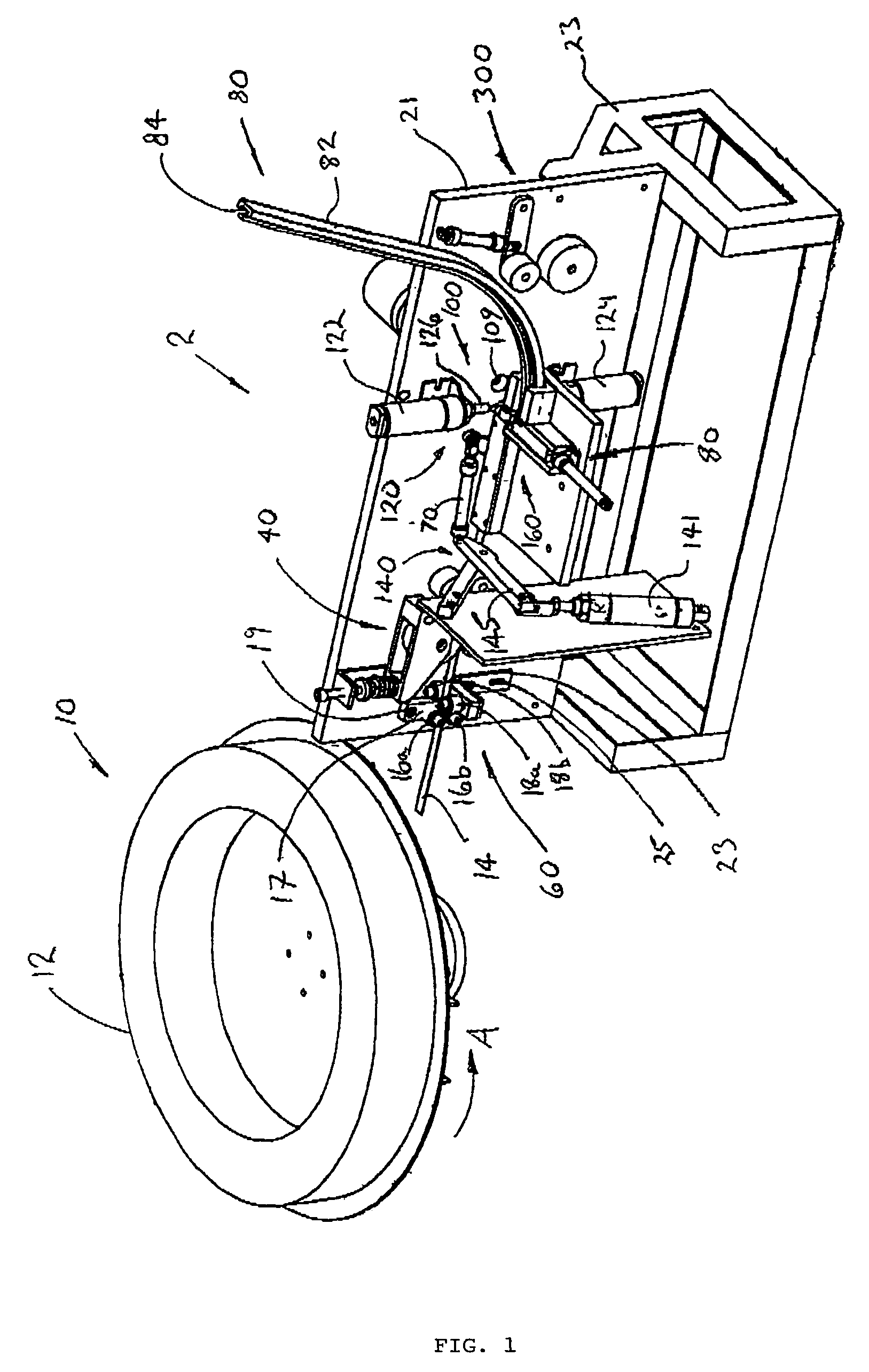
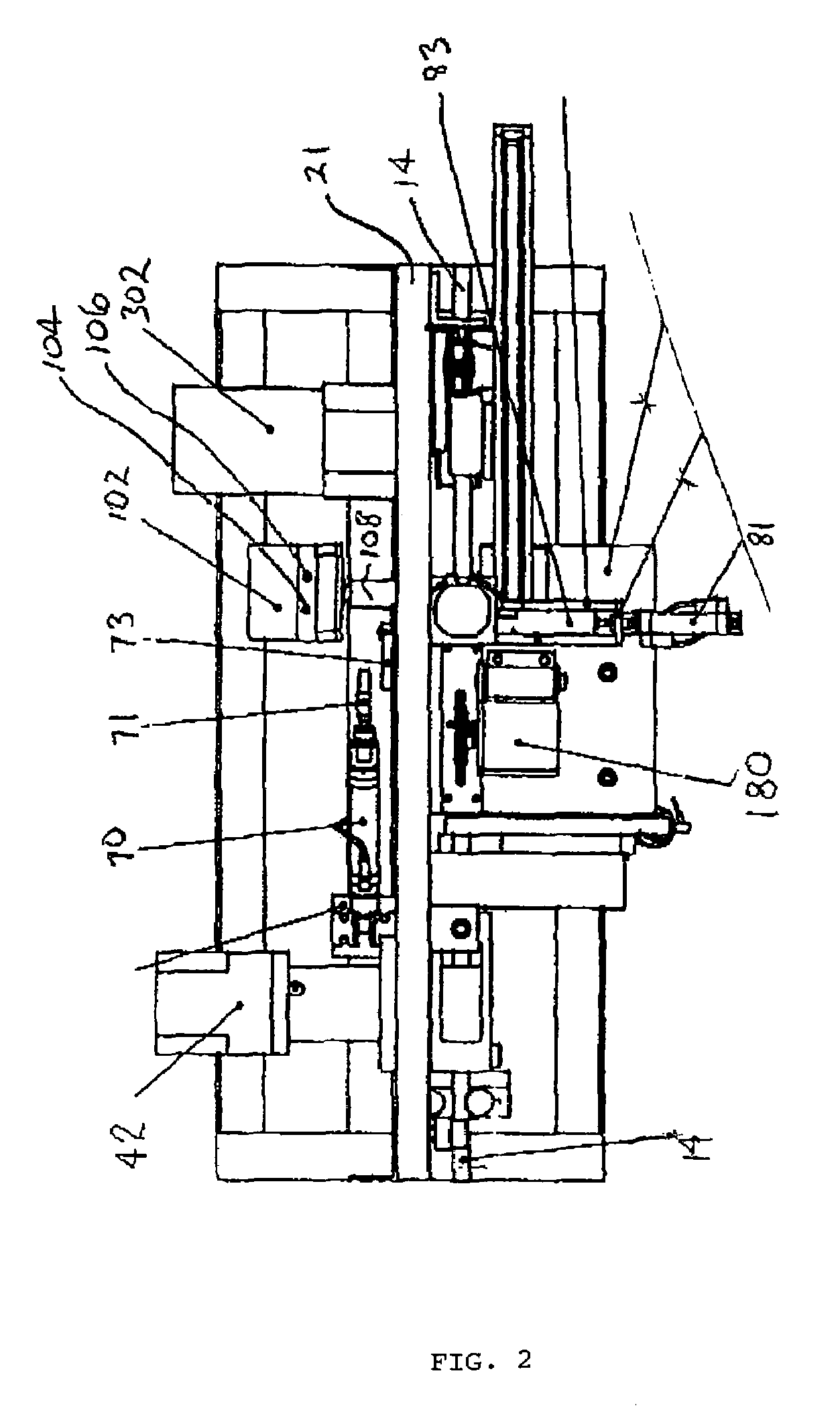
[0022]There is provided an apparatus for attaching a fastener or wing type seal, or “clip” to a band of desired length. As shown in FIGS. 1-3, the apparatus 2 includes a housing, source material retaining means 10, band feeding means 40, band end alignment means 60, clip positioning means 80, band bending means 100, band and clip crimping or compressing means 120, band cutting means 140, protective guard means and control system means.

[0023]Moreover vertical plate 21 is attached to a frame structure 23 to support the device 2 either on the ground, back of a truck or the like.

[0024]The source material retaining means 10 may be a spool 12 or other portable means. In oth...


PUM

PropertyMeasurementUnit
lengthaaaaaaaaaa
lengthaaaaaaaaaa
cut lengthaaaaaaaaaa

Abstract

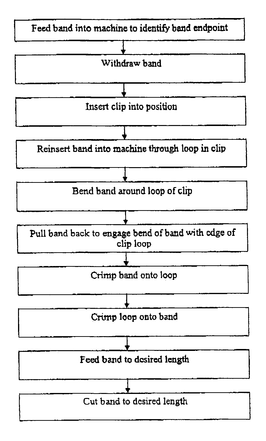
A device and method is disclosed for manufacturing a band of a desired length with a fastener attached to the band. Generally, metal band material is fed from a spindle on the device until the end of the band material is detected by the device. The device includes a positioning component that places the fastener at the desired location of the band, which is then looped through the fastener. The device then crimps the fastener to the band, positions the band at its desired length, and cuts the band to the desired length.

Description

FIELD OF INVENTION[0001]The present invention relates generally to banding systems, and more particularly to a device and method for automatically measuring, cutting and attaching a clip to a band.BACKGROUND TO THE INVENTION[0002]In the oil, gas and chemical refinery industries, there is a requirement for insulation to be wrapped around pipes. The insulation serves to conserve energy by limiting heat exchange with the surrounding atmosphere. The insulation is traditionally held in place with jacketing which protects the insulation from deterioration, and metal bands placed approximately every twelve inches along the length of the insulated pipe. A particular installation may require a million or more feet of pipe to be insulated. As the pipe diameters and insulation thickness may vary, there is no standard band length which can be produced in advance. Rather, bands must be measured and cut on site to meet the requirements of the particular installation.[0003]There is a need for an a...

Claims


Application Information

Patent Timeline
Patent Type & Authority Patents(United States)
IPC IPC(8): B23P11/00B65D63/02
CPCB65B13/16F16L33/02Y10T29/49915Y10T24/1457Y10T29/49908Y10T29/49954
Inventor VERESCHAGIN, LAWRENCE WAYNE
Owner VERESCHAGIN LAWRENCE WAYNE
Learn More