Process for laying a strip continuously on a toroidal surface

a technology of toroidal surface and continuous laying, which is applied in the direction of process and machine control, mechanical control devices, instruments, etc., can solve the problems of pressure in the organisation of the manufacturing process, too cumbersome devices to use, and unsuitability

Inactive Publication Date: 2010-01-05
MICHELIN & CO CIE GEN DES ESTAB MICHELIN
View PDF10 Cites 17 Cited by
  • Summary
  • Abstract
  • Description
  • Claims
  • Application Information

AI Technical Summary

Benefits of technology

[0025]For this purpose, it is sufficient to calculate at each moment the values of the displacements of the laying head along axes XX′ and YY′, these values being dependent in fact on the instantaneous value of the tangency angle and the predetermined value of a constant pitch, generally substantially equal to the width of the strip, in order to obtain, on each rotation of the receiving surface, continuous displacement of said laying head in a direction parallel to the direction of the tangent TT′ at the point of contact between the application means and the receiving surface, in such a way that the distance between two consecutive turns is equal to the pitch value at all points of the circumference. The same automatic device is also capable of controlling the orientation of the laying head, also dependent solely on the variation of the tangency angle, so as to position the strip at a tangent to the receiving surface at the point of application, making the transverse direction of said strip parallel to the tangent TT′. This allows precise juxtaposition of each of the turns relative to the turns directly adjacent thereto, and deposition of a uniform layer on the receiving surface.

Problems solved by technology

However, there are situations in which these devices may be considered too cumbersome to use or unsuitable.
Under these conditions, there is no longer any question of using bonding rubbers in the form of precalendered rubber strips of the width of the receiving surface and laid as required on the latter, prior to laying of the tread, because the properties of the bonding rubber change too quickly, thus creating pressures in the organisation of the manufacturing process due to the need to limit storage and waiting times.

Method used


Image

  • Process for laying a strip continuously on a toroidal surface
  • Process for laying a strip continuously on a toroidal surface
  • Process for laying a strip continuously on a toroidal surface

Examples


Embodiment Construction

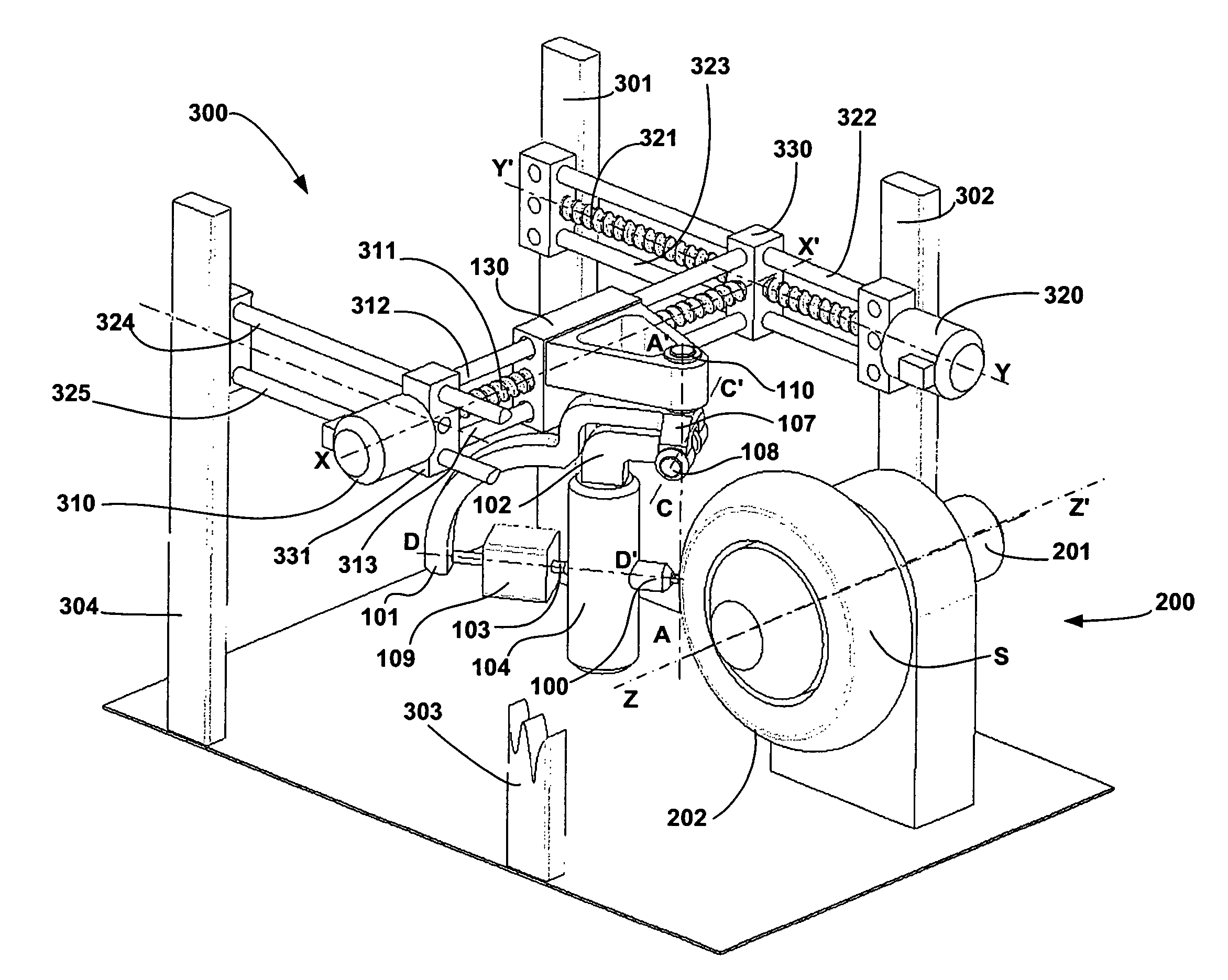
[0039]Hereinafter, the same reference numerals will be used to denote elements of the apparatus having identical functions, such as represented in FIGS. 1 to 9.

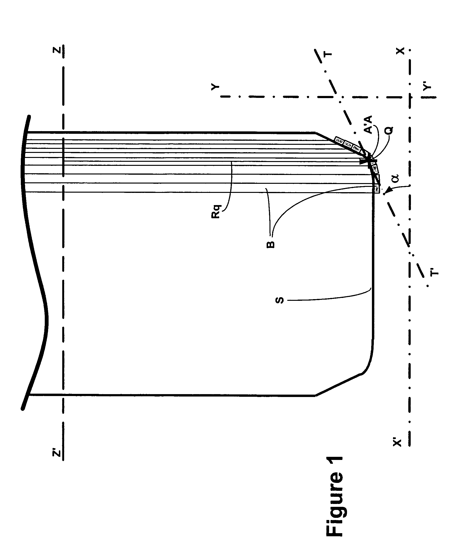
[0040]FIG. 1 illustrates the respective positions of the locating axes useful in describing an apparatus according to the invention.

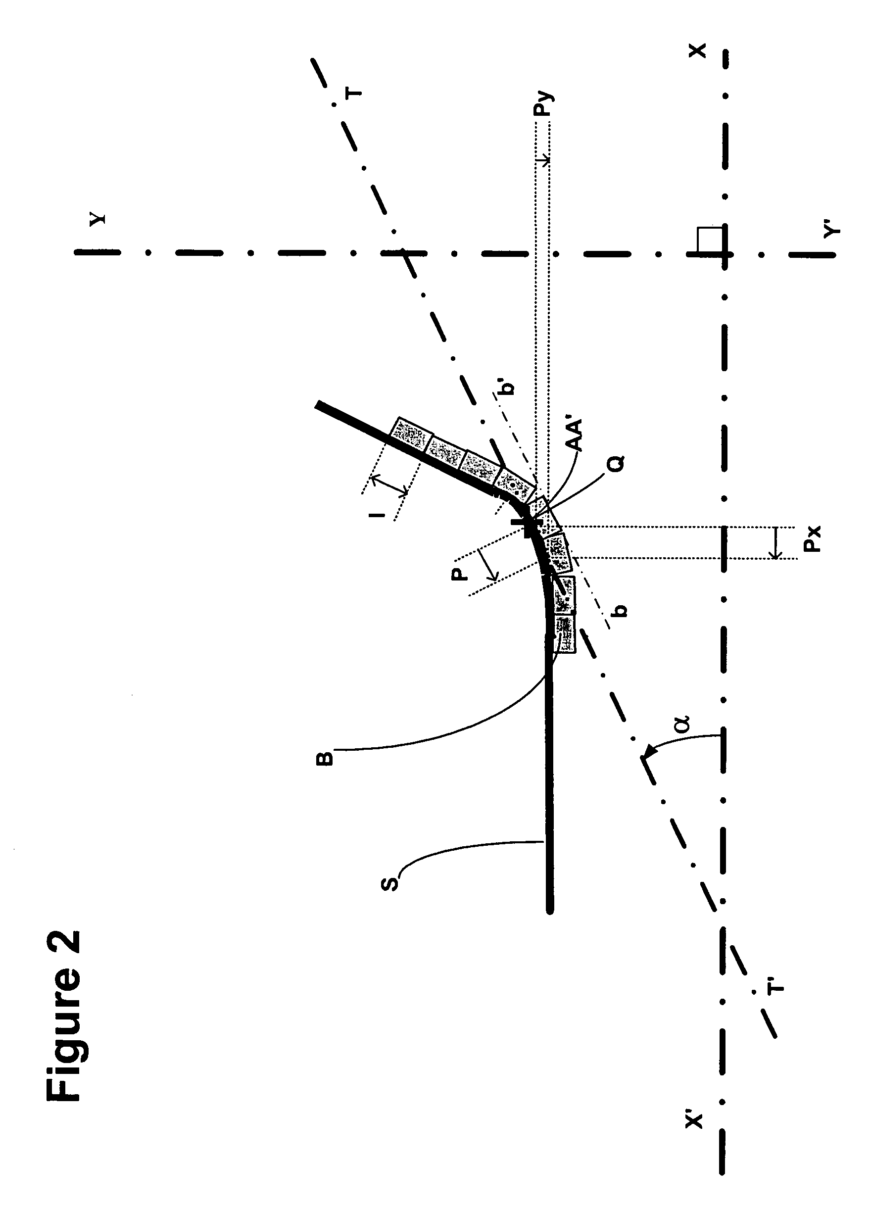
[0041]With reference to the axis of rotation ZZ′ of the receiving surface S, the axes XX′ and YY′ are respectively successively positioned parallel to the axis ZZ′ and parallel to a radial direction passing through the point Q corresponding substantially to the centre of contact between the application means 112 for the strip B and the receiving surface S. The direction YY′ is thus perpendicular to the axes XX′ and ZZ′, and the plane formed by the directions XX′ and YY′ passing through the point Q is an equatorial plane passing through the axis ZZ′, whose intersection with the surface S delimits the transverse profile of the latter.

[0042]The tangent TT′ to the transverse profile of the receiving ...


PUM

PropertyMeasurementUnit
tangency angleaaaaaaaaaa
distanceaaaaaaaaaa
widthaaaaaaaaaa

Abstract

A mechanism for laying a strip on a receiving surface rotating about a first axis. The mechanism includes a laying head moving along a second axis oriented parallel to the axis of rotation of the surface and along a third axis oriented parallel to a radial direction passing through the point of contact between the receiving surface and a strip applicator of the laying head. The laying head is rotatable about a front axis oriented substantially perpendicular to the second and third axes and passing through the contact point. the laying includes a device for estimating the value of the of the angle α formed by a tangent to the transverse profile of the surface and the second axis. The movements of the laying head are determined by the value of the angle α in such a way as to displace the laying head in a direction parallel to the tangent following the transverse profile of the receiving surface.

Description

[0001]The present application claims priority under 35 U.S.C. §119 to patent application Ser. No. 03 / 13763 filed in France on Nov. 21, 2003.BACKGROUND[0002]The present invention relates to a process for laying a strip continuously on a profile which is generally toroidal in shape.[0003]These days, continuous strip laying is widespread in the tyre industry and various processes have been described for depositing rubber strips or cord plies in the radial or circumferential direction.[0004]More particularly, the field of the invention relates to laying a strip continuously in the circumferential direction on the toroidal surface of a tyre casing, where the width of the strip is very much less than the width of the receiving surface and where, moreover, the thickness of the strip is very much less than its width.[0005]The processes suitable for performing these functions have been known for a long time and are described, by way of example, in patent nos. U.S. Pat. Nos. 3,251,722, 4,240,...

Claims


Application Information

Patent Timeline
Patent Type & Authority Patents(United States)
IPC IPC(8): B29D30/60B29C70/38B29C48/00B29C48/08B29D30/16B29D30/30
CPCB29C47/0021B29C70/32B29D30/1628B29D30/3028B29D30/60B29C70/386B29C47/00Y10T156/1712B29C48/00B29C48/08
Inventor NICOLAS, SERGECHEVAUX, NICOLASMONNEREAU, PATRICE
Owner MICHELIN & CO CIE GEN DES ESTAB MICHELIN
Why Eureka
Try Eureka