
Model verification support method, apparatus, and computer-readable recording medium storing program

a model verification and support method technology, applied in the field of large-scale integration verification technology, can solve the problems of inability to verify lsi (steps s, >3809/b>) and become complicated

Inactive Publication Date: 2009-12-29
FUJITSU LTD
View PDF16 Cites 1 Cited by
  • Summary
  • Abstract
  • Description
  • Claims
  • Application Information

AI Technical Summary

Benefits of technology

The present invention provides a verification supporting apparatus, method, and computer-readable recording medium for analyzing and modeling the requirements of a large-scale integration of a design object. The apparatus includes an analytical information receiving unit, a concept model generating unit, a function model generating unit, and a function model verifying unit. The method involves receiving analytical information, generating a concept model, extracting the division of modules, and verifying the properness of the division and concurrence of modules in the function model. The technical effects of the invention include improving the efficiency and accuracy of requirements analysis and modeling for large-scale integration of design objects.

Problems solved by technology

Moreover, since the functions conventionally realized by application software such as moving picture experts group (MPEG) and joint photographic experts group (JPEG) are now realized by hardware, functions of LSI are becoming complicated.
In the above design processing, however, verification of LSI (steps S3806 to S3809) can not be made unless the implementation (step S3805) is made.
This leads to a problem that, when an error is made due to an error of the specification, ambiguity of description, or misinterpretation by a designer at any upstream step of the design flow, the error is accumulated at steps subsequent to such step.
In the structural designing, architecture was determined on the desk and there was no method to ascertain its appropriateness.
Therefore, an increase in development risk could result in failure of a development project, to the loss of time and manpower spent in the development.
A special simulator (tools from electronic design automation (EDA) vendors such as VCS and NC-Sim) is required for applying simulation to HDL of the RTL 3850, and a slow simulation speed of the simulator leads to problems of decreased verification efficiency and a longer design period.
Especially when an LSI to be designed is of a large scale, occasionally the verification work could not be completed within a predetermined period because of a bottleneck of the slow simulation speed.
On the other hand, it is conceivable to increase the simulation speed by introducing an emulator capable of working at a speed thousands times as fast as the simulator, but the emulator is very expensive and increases verification expenses, and it is difficult to build the environment and debugging is difficult at the time of occurrence of a problem, resulting in increased verification period and a longer design period.

Method used


Image

  • Model verification support method, apparatus, and computer-readable recording medium storing program
  • Model verification support method, apparatus, and computer-readable recording medium storing program
  • Model verification support method, apparatus, and computer-readable recording medium storing program

Examples


Embodiment Construction

[0067]Exemplary embodiments according to the present invention will be explained in detail below with reference to accompanying drawings.

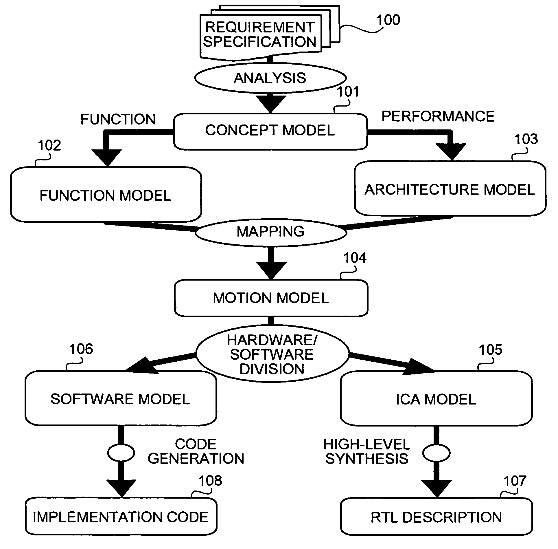
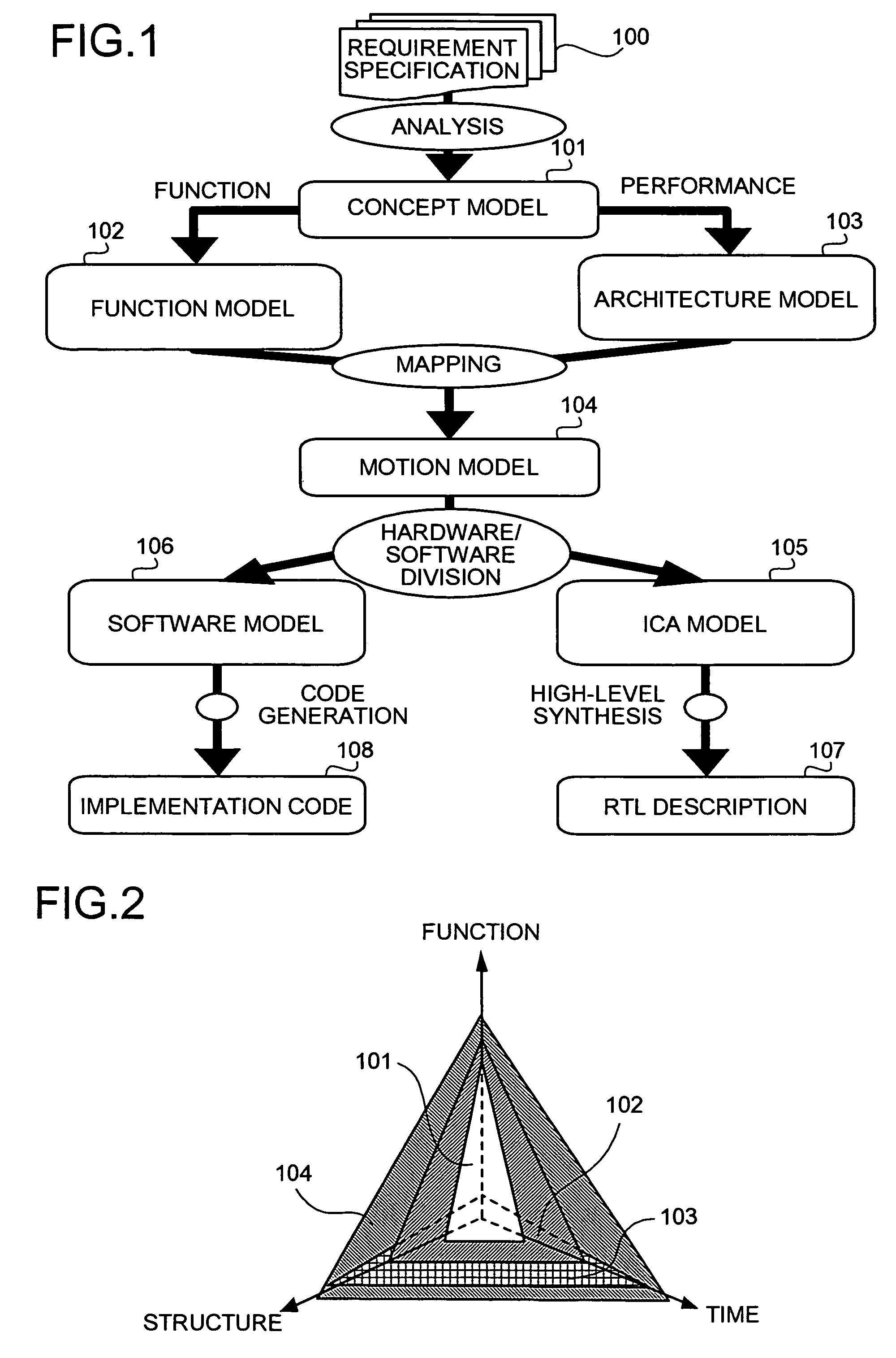
[0068]Description will now be made of a concept of a verification support according to the embodiment of the present invention. FIG. 1 is a conceptual illustration of the verification support according to the embodiment of the present invention.

[0069]As shown in FIG. 1, a designer applies an object-oriented analysis using unified modeling language (UML) to a requirement specification 100 from a customer of a system LSI including an object of design and performs modeling of results of analysis thereof as a concept model 101. The concept model 101 is a model representing the results of conceptual analysis of the object of design. The concept model 101 is a model entirely independent of implementation and specifically, is a model that has physical architecture and concept of time abstracted and is made by modeling with the center on basic functions of...


PUM


Abstract

A verification supporting apparatus includes a concept model generating unit, a function model verifying unit, a motion model verifying unit, and an ICA model verifying unit. The concept model generating unit generates a concept model aiming at a requirement specification of a customer to eliminate an error or misunderstanding of the specification at the initial stage of design. The function model verifying unit verifies a concurrent and parallel function model, to verify appropriateness of function module division and correctness of concurrence and parallelism. The motion model verifying unit verifies a motion model, to verify whether the design of architecture is appropriate and whether performance requirements are satisfied. The ICA model verifying unit verifies correctness of interface design.

Description

[0001]This application is a continuing application, filed under 35 U.S.C. §111(a), of International Application PCT / JP2004 / 009340, filed Jul, 1, 2004, the contents of which are incorporated herein by reference.BACKGROUND OF THE INVENTION[0002]1. Field of the Invention[0003]The present invention relates to a technology for supporting verification of a large-scale integration (LSI).[0004]2. Description of the Related Art[0005]In LSI design, a verification work of verifying whether an LSI works normally is essential. While the verification work is important to maintain high quality especially for the LSI for which a larger scale, a high performance, a higher speed, and lower power consumption are required, enhanced work efficiency by shortening a design period has conventionally been demanded.[0006]Especially in recent years, software and hardware are implemented on a single LSI and a system on chip (SoC) including not only conventional single-function hardware with an application spec...

Claims


Application Information

Patent Timeline
Patent Type & Authority Patents(United States)
IPC IPC(8): G06F17/50G06F17/10G06F9/45
CPCG06F17/5022G06F30/33
Inventor ZHU, QIANG
Owner FUJITSU LTD
Learn More