
Vibration gyro and the process of producing the same

a vibration gyro and vibration technology, applied in the direction of instruments, turn-sensitive devices, device material selection, etc., can solve the problem that the vibration in the out-of-plane direction may not be dramatically changed, and achieve the effect of reducing vibration leakage and simple working

Inactive Publication Date: 2009-12-29
CITIZEN WATCH CO LTD
View PDF5 Cites 6 Cited by
  • Summary
  • Abstract
  • Description
  • Claims
  • Application Information

AI Technical Summary

Benefits of technology

This approach effectively reduces out-of-plane vibration leakage, suppresses drift, and enables high-speed adjustment without causing damage to the resonator, resulting in a vibration gyro with improved noise and drift performance.

Problems solved by technology

Accordingly, there are effects that the worked surface is not etched by a large amount, when the detuning degree adjustment is performed in the subsequent step, and the leakage vibration in the out-of-plane direction may not be changed dramatically.

Method used


Image

  • Vibration gyro and the process of producing the same
  • Vibration gyro and the process of producing the same
  • Vibration gyro and the process of producing the same

Examples


Embodiment Construction

[0001]1. Field of the Invention

[0002]The present invention relates to a vibration gyro that is used to detect an angular velocity, and the process of producing the same.

[0003]2. Related Art

[0004]A vibration gyro is employed in a mechanism such as a camera shake compensation mechanism in a home video unit and a position detecting mechanism in a vehicle navigation system, so as to detect a vibration due to hand movement or a rotation angle of a vehicle.

[0005]According to the physical law, when viewed from a coordinate system rotating at the angular velocity O, a moving object receives a Coriolis force Fc in proportion to a relative velocity V of the object in a direction orthogonal to the velocity. A magnitude and a direction of the Coriolis force are expressed by the following equation:

Fc=2mV×O   (Equation 1)

[0006]In this equation, “m” represents a mass of the object on which the Coriolis force acts.

[0007]The vibration gyro is an angular velocity sensor that detects a rotation, and i...


PUM

PropertyMeasurementUnit
inclined angleaaaaaaaaaa

Abstract

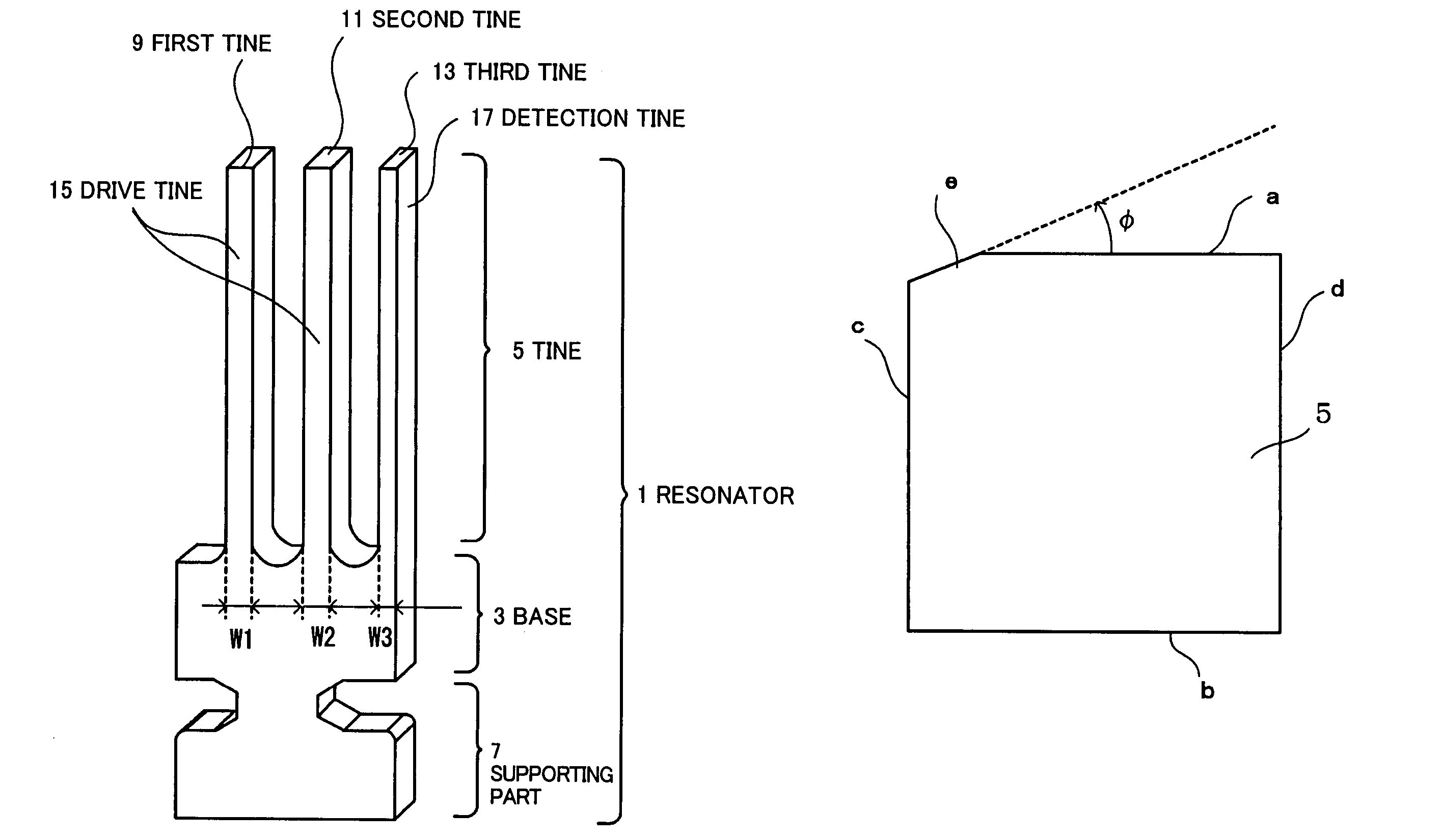
An inclination of an inclined surface formed by working a ridge of a resonator is set to be within a predetermined angular range, whereby a leakage of vibration in the out-of-plane direction is reduced, the leakage of vibration being generated according to the detuning degree adjustment. In addition, a single laser beam is irradiated onto the ridge at an incident angle within a predetermined angular range, whereby a simple working on the inclined surface is established for the leakage vibration adjustment. A degree of the leakage vibration of the resonator is determined based on a relationship with the drift amount that is a ratio of the angular velocity change, and the inclination of the inclined surface is set to be within a predetermined angular range, thereby suppressing the drift amount.

Description

DETAILED DESCRIPTION[0001]1. Field of the Invention[0002]The present invention relates to a vibration gyro that is used to detect an angular velocity, and the process of producing the same.[0003]2. Related Art[0004]A vibration gyro is employed in a mechanism such as a camera shake compensation mechanism in a home video unit and a position detecting mechanism in a vehicle navigation system, so as to detect a vibration due to hand movement or a rotation angle of a vehicle.[0005]According to the physical law, when viewed from a coordinate system rotating at the angular velocity O, a moving object receives a Coriolis force Fc in proportion to a relative velocity V of the object in a direction orthogonal to the velocity. A magnitude and a direction of the Coriolis force are expressed by the following equation:Fc=2mV×O   (Equation 1)[0006]In this equation, “m” represents a mass of the object on which the Coriolis force acts.[0007]The vibration gyro is an angular velocity sensor that detec...

Claims


Application Information

Patent Timeline
Patent Type & Authority Patents(United States)
IPC IPC(8): G01P9/04H01L41/22G01C19/56G01C19/5628G01C19/5663H01L41/08H01L41/18H01L41/335
CPCG01C19/5607Y10T29/4984Y10T29/42
Inventor YAMAMOTO, IZUMIMORIYA, TAKASHIIKEDA, TOMOOMURAKAMI, ATSUSHISHIOJI, AKIHIRO
Owner CITIZEN WATCH CO LTD
Learn More