Sensor unit having an adhesive member connected to an outer edge of a sensor device and placed continuously in an area overlapping a sensor device
a sensor unit and adhesive member technology, applied in the direction of acceleration measurement using interia force, measurement apparatus housing, instruments, etc., can solve the problems of inability to suppress the change in the detection accuracy is reduced in some cases, and the detection accuracy is reduced, so as to reduce the dimension of the sensor unit in the height direction, suppress the reduction of the detected value of the amount of inertia, and the effect of high impact resistan
- Summary
- Abstract
- Description
- Claims
- Application Information
AI Technical Summary
Benefits of technology
Problems solved by technology
Method used
Image
Examples
first embodiment
Configuration of Sensor Unit
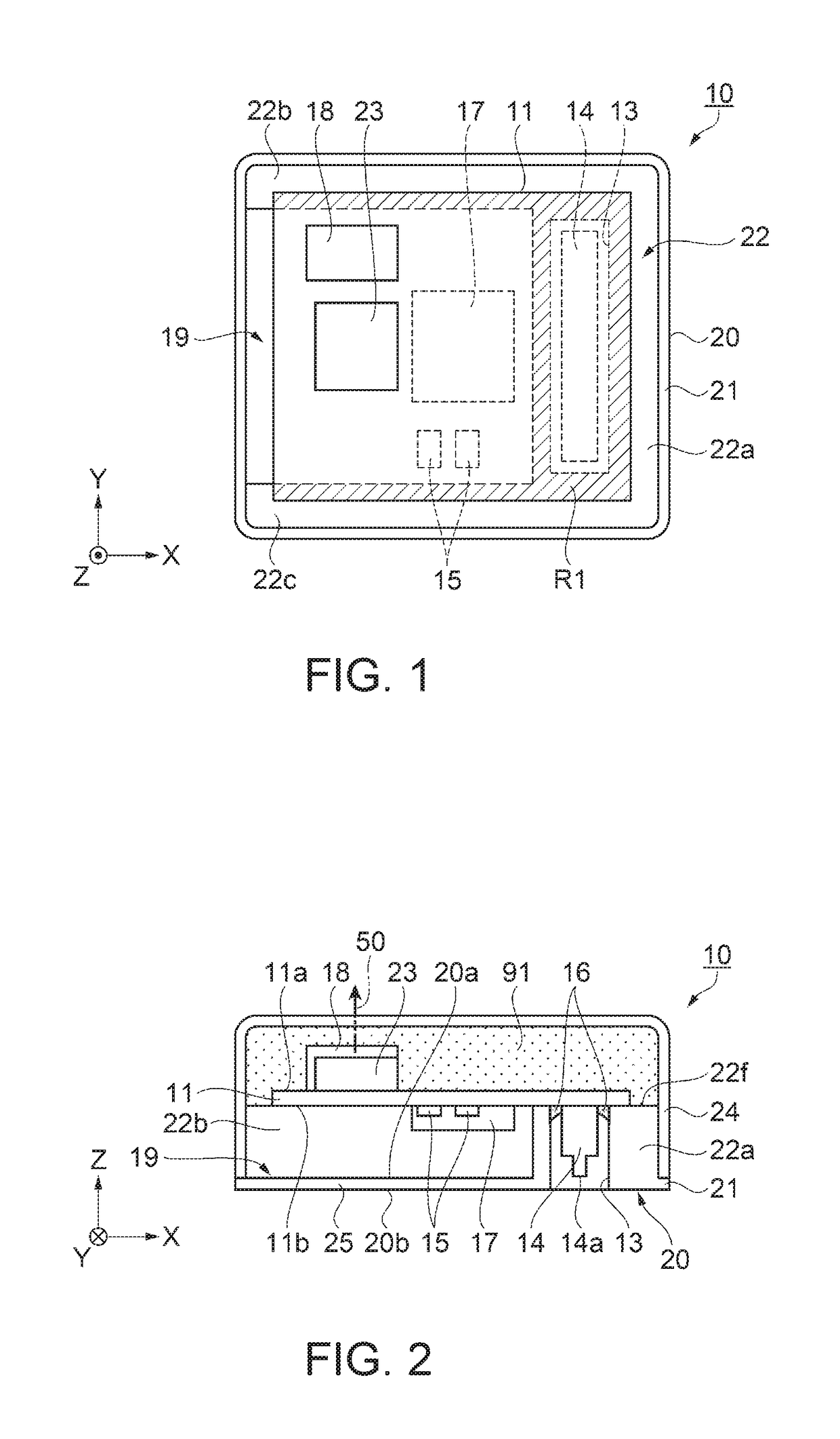
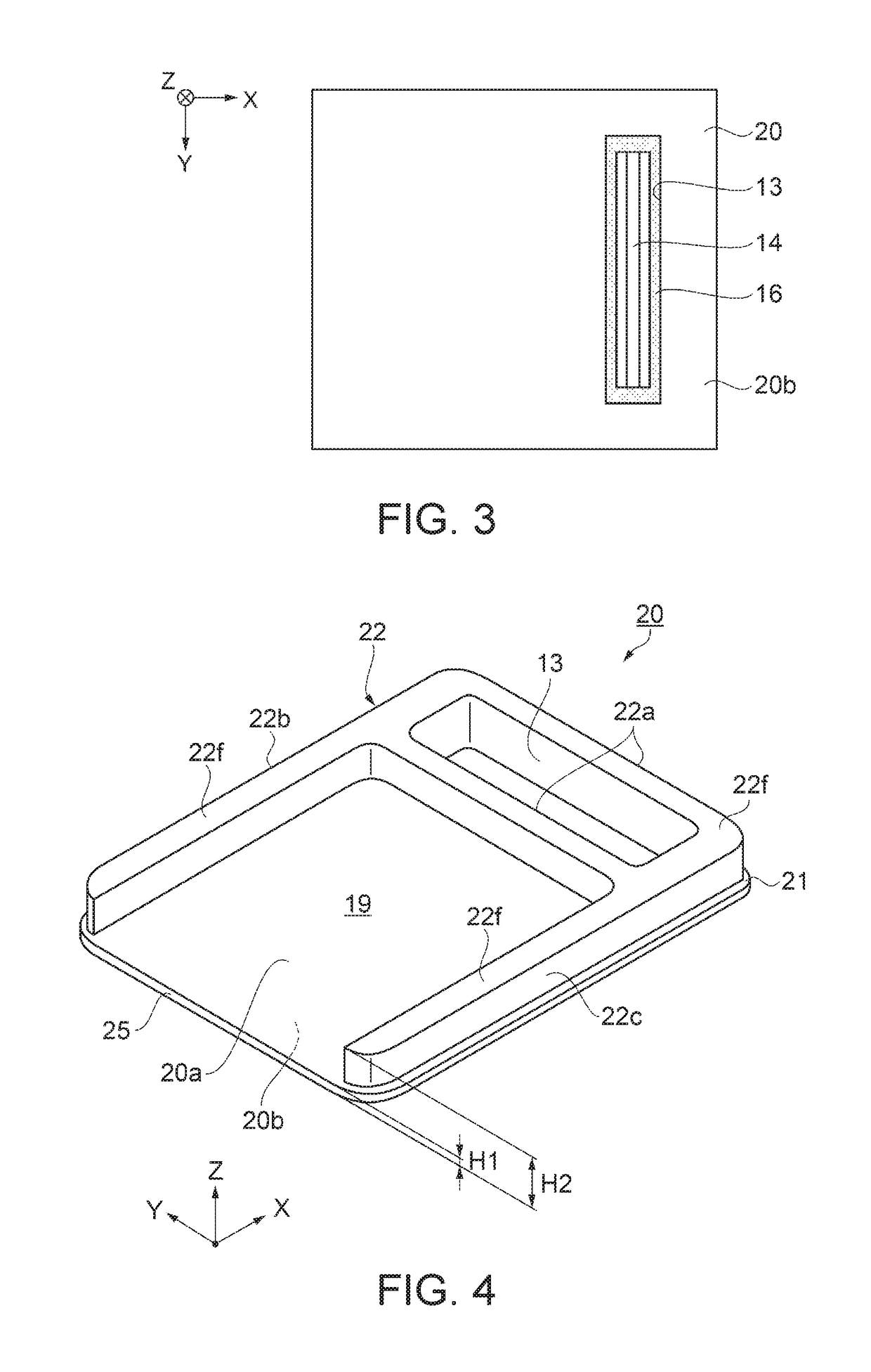
[0048]FIGS. 1 to 3 are diagrams schematically showing an external appearance of a sensor unit according to a first embodiment, in which FIG. 1 is a plan view, FIG. 2 is a front cross-sectional view, and FIG. 3 is a bottom plan view. In FIG. 1, a cap as a case member is omitted for clarity of illustration. FIG. 4 is a perspective view showing an overview of a pedestal in the first embodiment.
[0049]As shown in FIG. 1, the sensor unit 10 according to the first embodiment includes a substrate 11 provided with a first sensor device 23 as a sensor device and a connector 14 connected to the first sensor device 23, and the pedestal 20 on which the substrate 11 is placed and which includes a through-hole 13 as an opening through which the connector 14 is exposed. Moreover, the sensor unit 10 includes the cap 24 as a case member (lid member) connected to the pedestal 20 and covering the substrate 11. The first sensor device 23 is disposed in a position overlapping,...
second embodiment
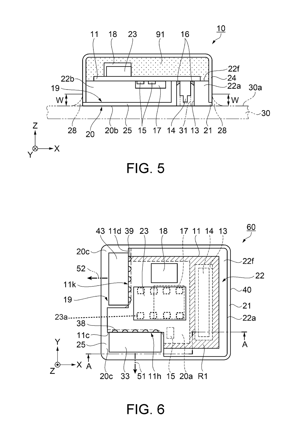
[0077]Next, a second embodiment of a sensor unit will be described with reference to FIGS. 6 to 9. FIGS. 6 to 8 show a schematic configuration of the sensor unit according to the second embodiment, in which FIG. 6 is a plan view, FIG. 7 is a cross-sectional view taken along the line A-A of FIG. 6, and FIG. 8 is a bottom plan view. In FIG. 6, for clarity of illustration, the cap as a case member is omitted. FIG. 9 is a perspective view showing an overview of a pedestal in the second embodiment. Configurations similar to those of the first embodiment described above are denoted by the same reference numerals and signs. Moreover, the description of the same configurations may be omitted.
[0078]As shown in FIGS. 6 to 8, the sensor unit 60 according to the second embodiment includes the substrate 11 provided with the first sensor device 23 and the second sensor device 18 as sensor devices, a third sensor device 33 and a fourth sensor device 43 as side-surface disposed sensor devices, and ...
example 1
[0127]Next, preparation of sensor units of Example 1 and a stability evaluation result of the acceleration measured value after thermal stress application in the sensor units will be described. In Example 1, four levels of sensor units 110 were formed using, in addition to the members using the common materials described above, the same epoxy-based resin (linear expansion coefficient: 41 ppm / ° C.) as that of the comparative example described above for the adhesive member 91, and also using the following four levels of materials as the material of the cap 24.
[0128]1a). Aluminum alloy (linear expansion coefficient: 23 ppm / ° C.)
[0129]1b). Brass (linear expansion coefficient: 20 ppm / ° C.)
[0130]1c). Stainless steel (linear expansion coefficient: 10.4 ppm / ° C.)
[0131]1d). Quartz (linear expansion coefficient: 10.3 ppm / ° C.)
[0132]As a result of conducting the above-described stability evaluation of the acceleration measured value on each of the samples...
PUM
 Abstract
Description
Claims
Application Information
 - R&D
- Intellectual Property
- Life Sciences
- Materials
- Tech Scout
- Unparalleled Data Quality
- Higher Quality Content
- 60% Fewer Hallucinations
Browse by: Latest US Patents, China's latest patents, Technical Efficacy Thesaurus, Application Domain, Technology Topic, Popular Technical Reports.
© 2025 PatSnap. All rights reserved.Legal|Privacy policy|Modern Slavery Act Transparency Statement|Sitemap|About US| Contact US: help@patsnap.com


