Vibrator, oscillator, electronic apparatus, moving object, and method of manufacturing vibrator
a technology of vibrating device and oscillating device, which is applied in the direction of electrostatic generator/motor, line/current collector details, electrical apparatus, etc., can solve the problems of reducing vibration efficiency, difficult to obtain stable vibration characteristics or desired vibration characteristics, and unable to achieve stable vibration characteristics and desired vibration characteristics. , to achieve the effect of superior space utility and high vibration efficiency
- Summary
- Abstract
- Description
- Claims
- Application Information
AI Technical Summary
Benefits of technology
Problems solved by technology
Method used
Image
Examples
first embodiment
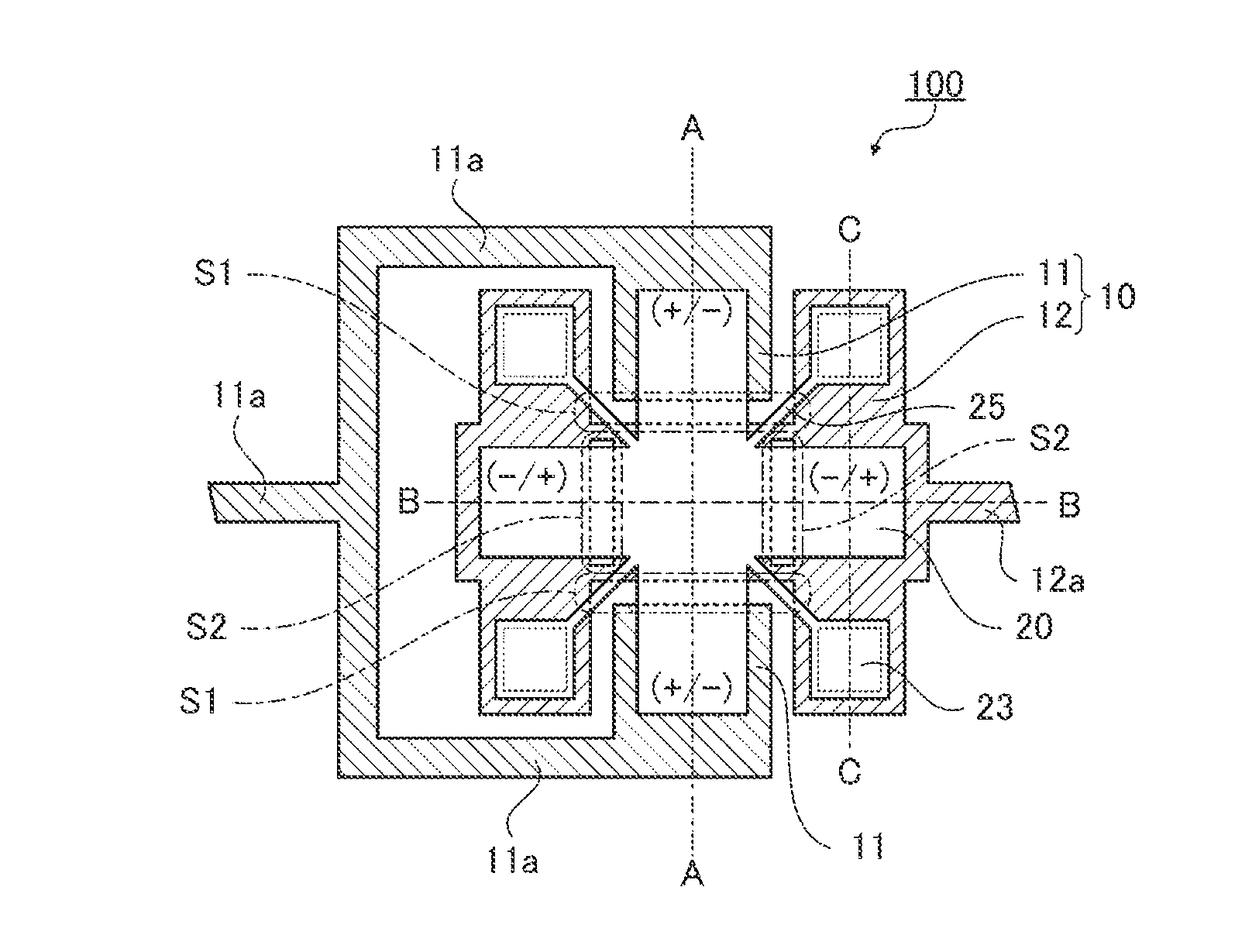
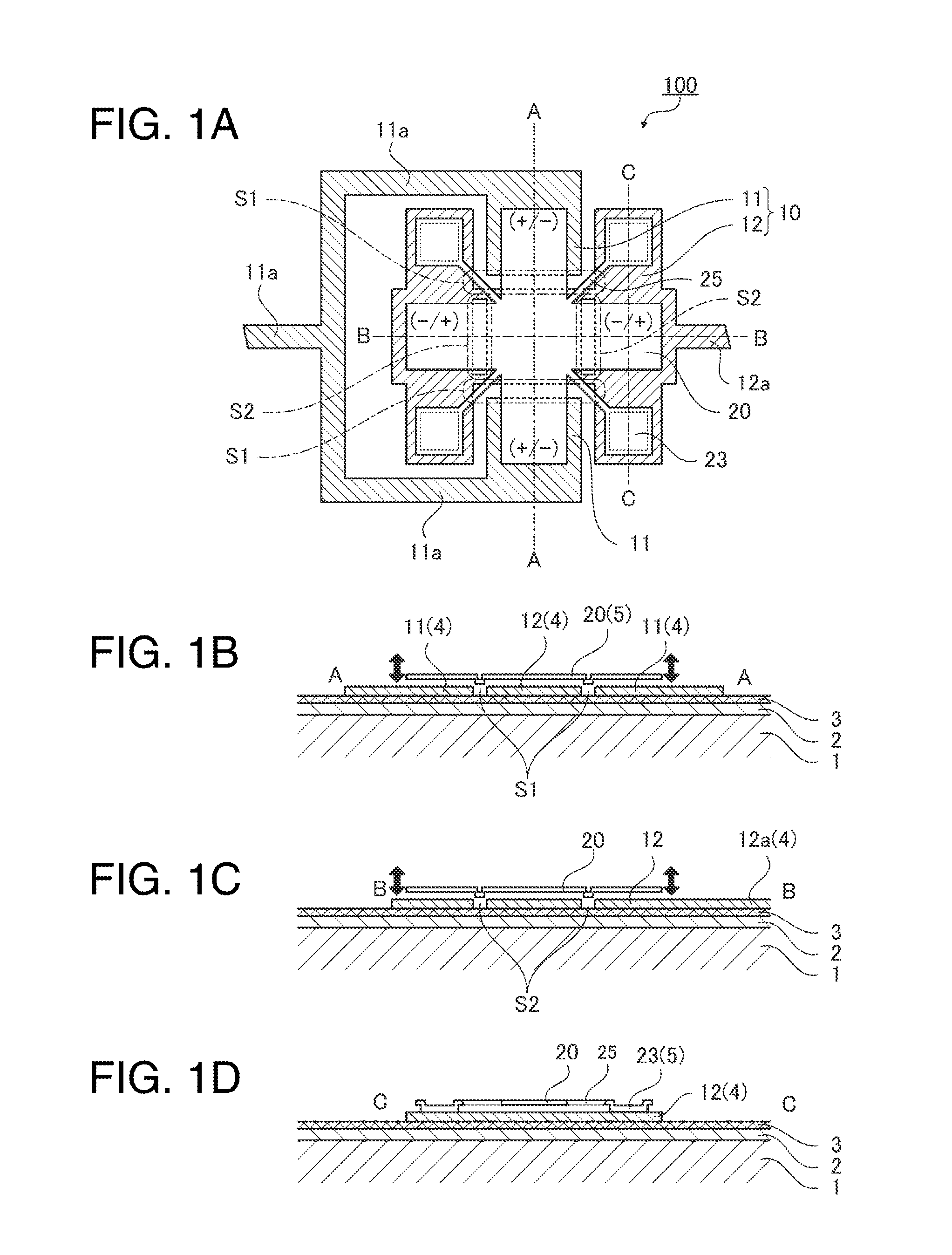
[0050]Firstly, an MEMS vibrator 100 as a vibrator according to the first embodiment will be explained.
[0051]FIG. 1A is a plan view of the MEMS vibrator 100, FIG. 1B is an A-A cross-sectional view of FIG. 1A, FIG. 1C is a B-B cross-sectional view of FIG. 1A, and FIG. 1D is a C-C cross-sectional view of FIG. 1A.
[0052]The MEMS vibrator 100 is an electrostatic beam-type vibrator provided with a stationary electrode (a lower electrode) formed on the substrate, and a movable electrode (an upper electrode) formed separately from the substrate and the stationary electrode. The movable electrode is formed separately from the substrate and the stationary electrode by etching a sacrifice layer stacked on the principal surface of the substrate and the stationary electrode.
[0053]It should be noted that the sacrifice layer is a layer tentatively formed of an oxide film or the like, and is removed by etching after forming a necessary layer above, below, or the periphery of the sacrifice layer. By ...
second embodiment
[0078]Then, as a second embodiment, a method of manufacturing the vibrator (the MEMS vibrator 100) according to the first embodiment will be explained. It should be noted that in the explanation, the constituents identical to those in the embodiment described above will be denoted with the same reference symbols, and any redundant explanation will be omitted.
[0079]FIGS. 4A through 4G are process charts sequentially showing the method of manufacturing the MEMS vibrator 100. The states of the MEMS vibrator 100 in the respective processes are shown using the A-A cross-sectional view and the C-C cross-sectional view in FIG. 1A.
[0080]The method of manufacturing a vibrator according to the present embodiment is characterized by including a process of stacking the first conductive material layer 4 on the principal surface of the substrate 1, a first layer forming process of shaping the first conductive material layer 4 to form the lower electrodes 10 (the first lower electrode 11 and the s...
third embodiment
[0094]Then, as a third embodiment, a method of manufacturing the vibrator (the MEMS vibrator 100) according to the first embodiment will be explained. It should be noted that in the explanation, the constituents identical to those in the embodiment described above will be denoted with the same reference symbols, and any redundant explanation will be omitted.
[0095]FIGS. 5A through 5F are process charts sequentially showing the method of manufacturing the MEMS vibrator 100. The states of the MEMS vibrator 100 in the respective processes are shown using the A-A cross-sectional view and the B-B cross-sectional view in FIG. 1A.
[0096]The method of manufacturing a vibrator according to the present embodiment is characterized in that the sacrifice layer 7 is planarized to thereby reduce or eliminate the unevenness provided to the upper electrode 20 compared to the method of manufacturing a vibrator according to the second embodiment.
[0097]The method of manufacturing a vibrator according to ...
PUM
| Property | Measurement | Unit |
|---|---|---|
| area | aaaaa | aaaaa |
| conductive | aaaaa | aaaaa |
| thickness | aaaaa | aaaaa |
Abstract
Description
Claims
Application Information
 - R&D
- Intellectual Property
- Life Sciences
- Materials
- Tech Scout
- Unparalleled Data Quality
- Higher Quality Content
- 60% Fewer Hallucinations
Browse by: Latest US Patents, China's latest patents, Technical Efficacy Thesaurus, Application Domain, Technology Topic, Popular Technical Reports.
© 2025 PatSnap. All rights reserved.Legal|Privacy policy|Modern Slavery Act Transparency Statement|Sitemap|About US| Contact US: help@patsnap.com


