Al technical title is built by PatSnap Al team. It summarizes the technical point description of the patent document.
a filter and variation technology, applied in the field of rf filters, can solve the problems of no technique offered that adjusts the filter in the signal path, and the operation is not ideal,
Inactive Publication Date: 2009-12-22
CSR TECH INC
View PDF16 Cites 36 Cited by
Summary
Abstract
Description
Claims
Application Information
AI Technical Summary
This helps you quickly interpret patents by identifying the three key elements:
Problems solved by technology
Method used
Benefits of technology
Problems solved by technology
Thus, capacitor variation can cause frequency response shifts in filters, causing non-ideal operation.
Currently, there is no technique offered that adjusts filters in the signal path based, at least in part, on LC variation during operation of a tuner.
Method used
Image
Click on the blue label to locate the original text in one second.
Reading with bidirectional positioning of images and text.
Examples
Embodiment Construction
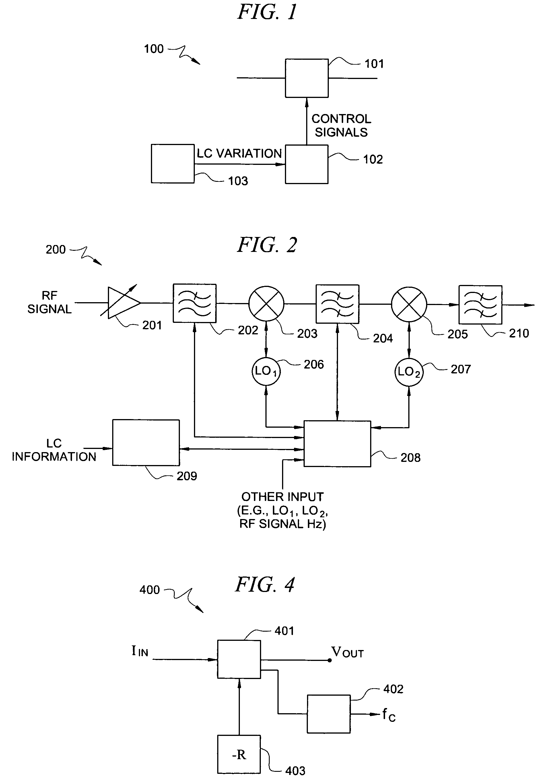
[0015]FIG. 1 is an illustration of exemplary system 100 adapted according to one embodiment of the invention. System 100 include filter 101, control unit 102, and Inductive / Capacitive (LC) variation unit 103. LC variation unit 103 is adapted to measure a variation of LC circuitry. Control unit 102 is adapted to adjust filter 101 based at least in part on the measured LC variation. While filter 101, control unit 102, and LC variation unit 103 are shown as separate items, the invention is not so limited, as various embodiments may combine one or more of the items. Also control unit 102, and LC variation unit 103 may be hardware-based, software based, or a combination thereof.
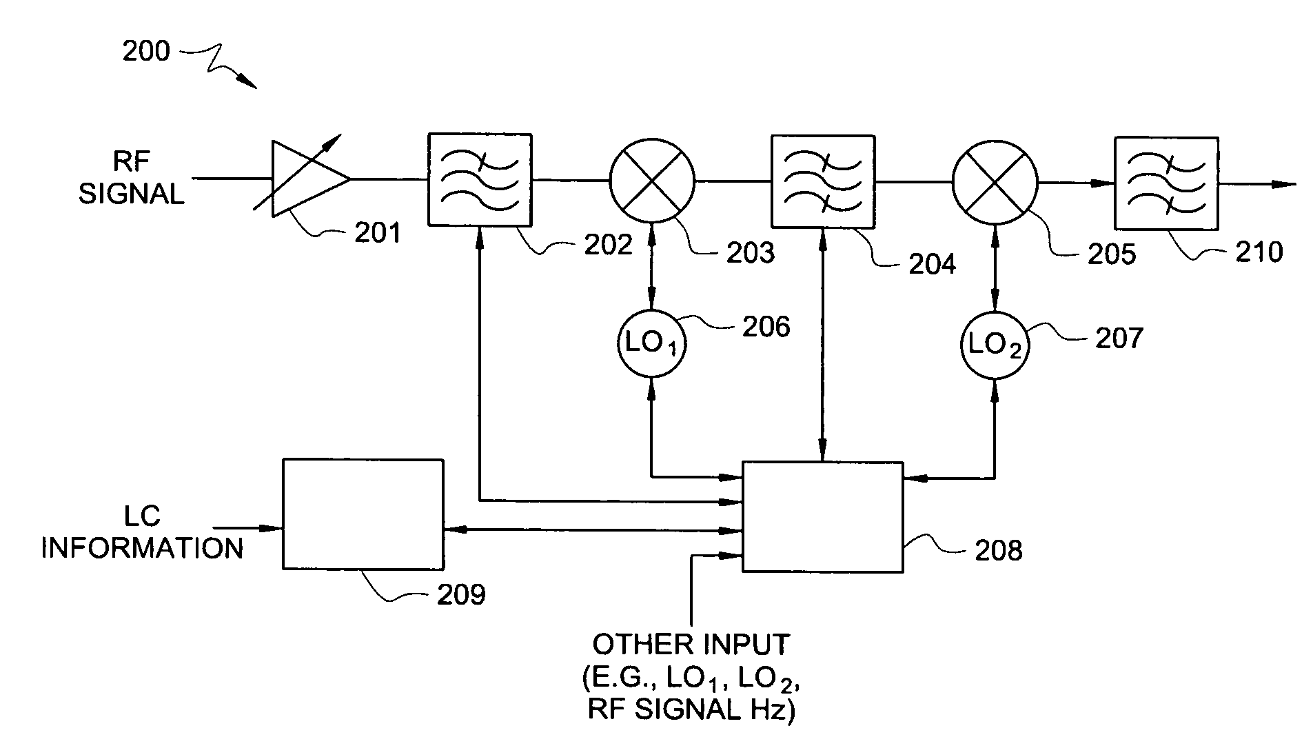
[0016]FIG. 2 is an illustration of exemplary tuner system 200 adapted according to one embodiment of the invention. System 200 includes Low Noise Amplifier (LNA) 201, receiving as input a Radio Frequency (RF) signal. The output of LNA 201 is sent to RF filter 202, which filters out some unwanted frequencies and se...
PUM
Abstract
A system for processing a signal comprises a Radio Frequency (RF) signal tuner, one or more filters in a signal path of the RF tuner each based on Inductive / Capacitive (LC) circuitry, a variation unit operable to measure a variation of the LC circuitry, and a frequency control unit adapted to adjust the one or more filters based on the LC variation during operation of the tuner.
Description
CROSS-REFERENCE TO RELATED APPLICATIONS[0001]This application is related to U.S. patent application Ser. No. 11 / 513,521, filed Aug. 31, 2006, entitled “SYSTEMS AND METHODS FOR DETECTING CAPACITOR PROCESS VARIATION,” and to U.S. patent application Ser. No. 11 / 513,550, filed Aug. 31, 2006, entitled “SYSTEMS AND METHODS FOR FILTER CENTER FREQUENCY LOCATION,” the disclosures of which are hereby incorporated herein by reference.TECHNICAL FIELD[0002]This description relates, in general, to RF filters, and, more specifically, to adjusting a frequency response of one or more filters based at least in part on LC variation.BACKGROUND OF THE INVENTION[0003]Currently, it is common to form various systems on semiconductor chips. General purpose processors, digital signal processors, Application Specific Integrated Circuits (ASICs), and the like are manufactured by forming a variety of transistors, memory elements, resistors, capacitors, inductors, etc., on a semiconductor substrate.[0004]The pro...
Claims
Application Information
Patent Timeline
Application Date:The date an application was filed.
Publication Date:The date a patent or application was officially published.
First Publication Date:The earliest publication date of a patent with the same application number.
Issue Date:Publication date of the patent grant document.
PCT Entry Date:The Entry date of PCT National Phase.
Estimated Expiry Date:The statutory expiry date of a patent right according to the Patent Law, and it is the longest term of protection that the patent right can achieve without the termination of the patent right due to other reasons(Term extension factor has been taken into account ).
Invalid Date:Actual expiry date is based on effective date or publication date of legal transaction data of invalid patent.