Contour mode resonators with acoustic reflectors

a technology of acoustic reflectors and convex resonators, which is applied in piezoelectric/electrostrictive/magnetostrictive devices, electrostatic generators/motors, piezoelectric/electrostriction/magnetostriction machines, etc. it can solve the problems of tethers providing relatively poor heat sinking to the substrate, limiting the number of fbars, and limiting the number of resonators

Active Publication Date: 2008-06-10
NAT TECH & ENG SOLUTIONS OF SANDIA LLC
View PDF8 Cites 30 Cited by
  • Summary
  • Abstract
  • Description
  • Claims
  • Application Information

AI Technical Summary

Benefits of technology

[0010]The substrate can comprise silicon (e.g. a silicon substrate, or a silicon-on-insulator substrate). This is particularly advantageous when the MEM resonator is to be fabricated with CMOS circuitry on the same substrate.

Problems solved by technology

However, such FBARs are limited in that multiple resonators operating at different frequencies cannot easily be fabricated on a common substrate since the film thickness of the piezoelectric material sets the operating frequency so that all the FBARs formed on a common substrate generally have the same operating frequency.
The tethers provide relatively poor heat sinking to the substrate, and this limits the power handling capability of these contour mode resonators.
Additionally, the tethers provide a discontinuity which can distort the shape of the contour mode and produce spurious modes even when notching about the tethers is used.

Method used


Image

  • Contour mode resonators with acoustic reflectors
  • Contour mode resonators with acoustic reflectors
  • Contour mode resonators with acoustic reflectors

Examples


Embodiment Construction

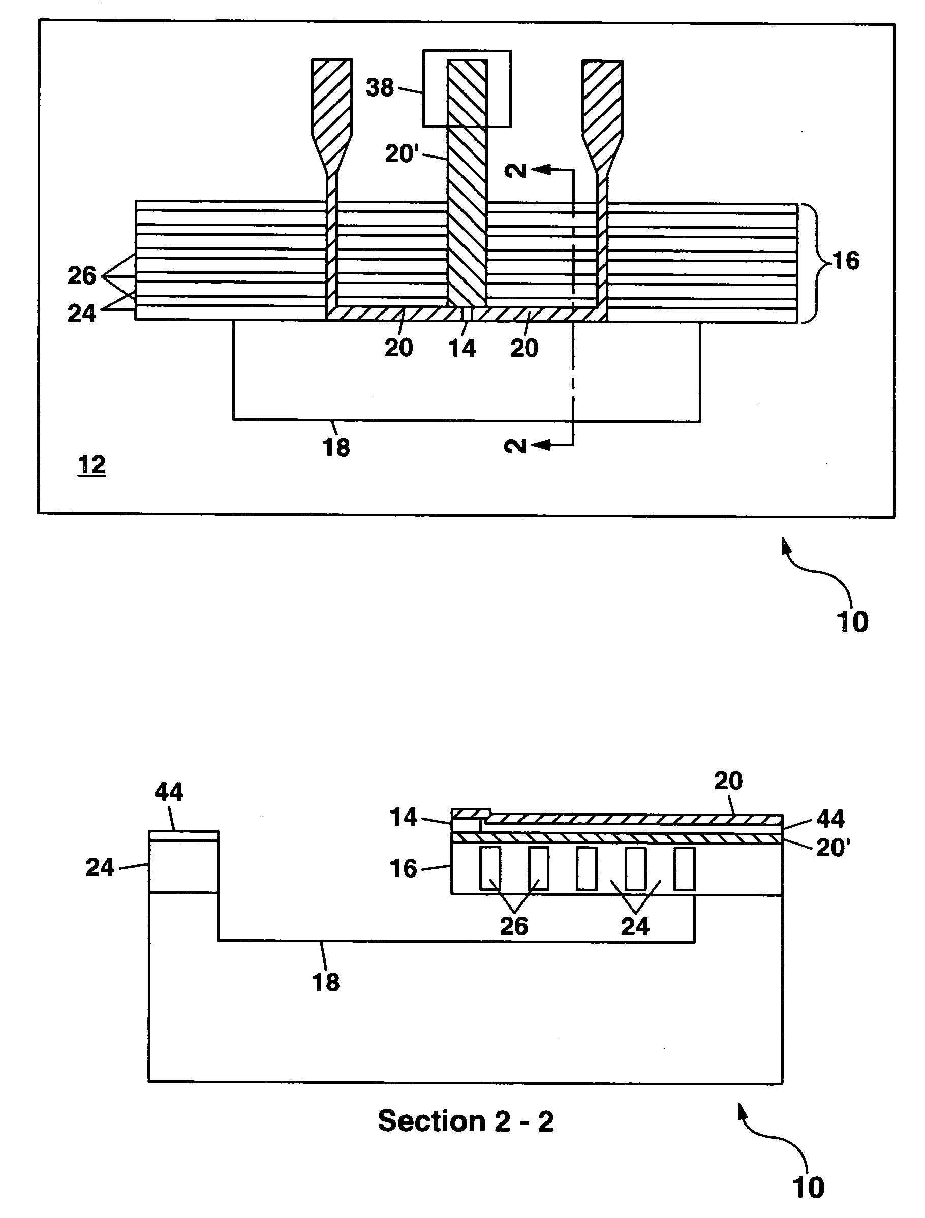
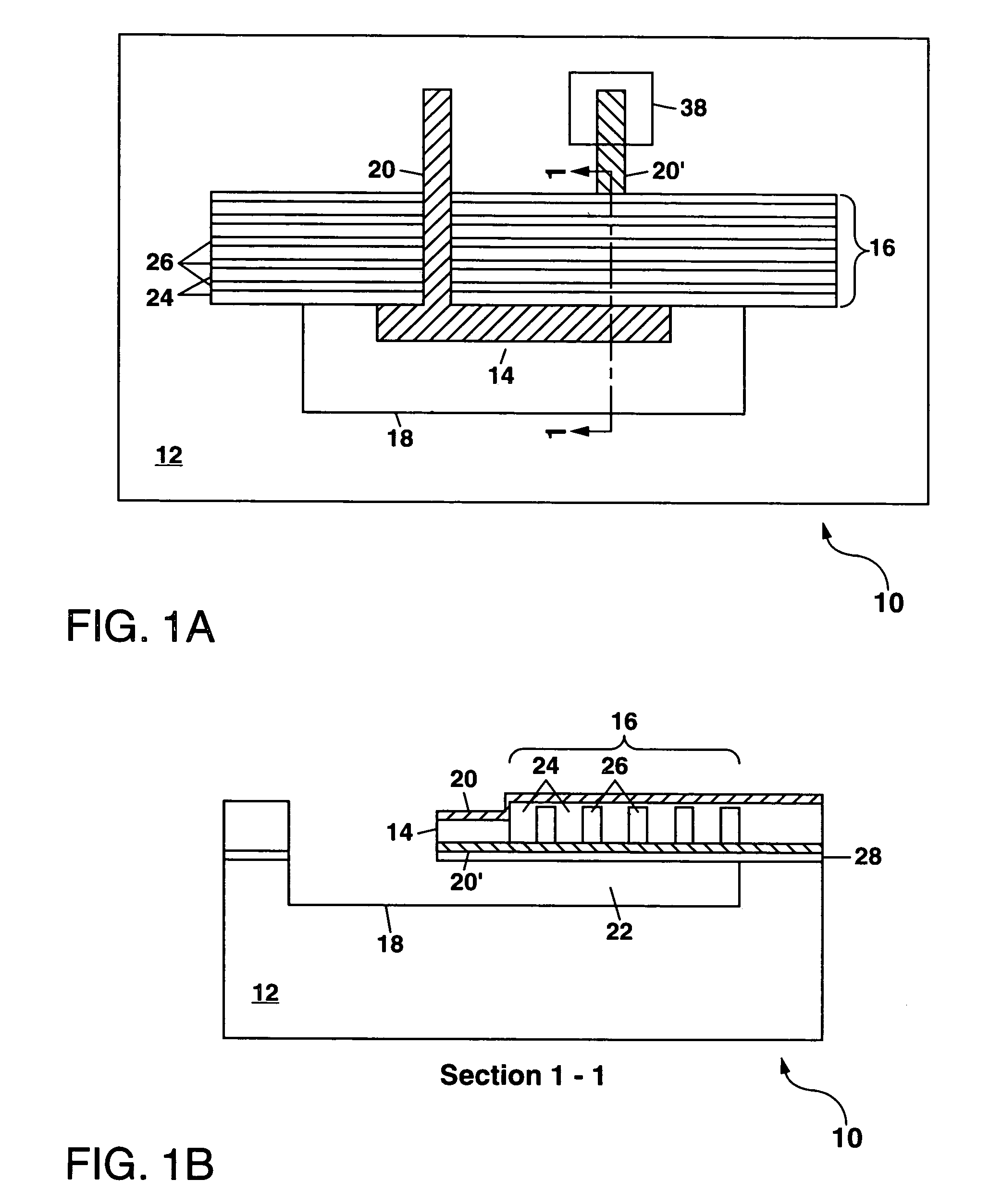
[0026]Referring to FIGS. 1A and 1B, there is shown a schematic plan view and a schematic cross-section view, respectively, of a first example of a MEM resonator 10 formed according to the present invention. The MEM resonator 10 comprises a substrate 12 with an acoustic resonator 14 suspended thereon by an acoustic reflector 16. The acoustic resonator 14 and at least a part of the acoustic reflector 16 extend outward over a cavity 18 formed in the substrate 12, with the acoustic reflector 16 being formed as a cantilevered plate extending substantially parallel to the substrate 12 and having a thickness of up to a few microns (e.g. 1-5 μm). In this way, the acoustic resonator 14 can be acoustically isolated from the substrate 12 by the acoustic reflector 16 while still being thermally coupled to the substrate 12 through the acoustic reflector 16. Any heat generated within the acoustic resonator 14 by electrical actuation thereof can be dissipated through the acoustic reflector 16 to t...


PUM


Abstract

A microelectromechanical (MEM) resonator is disclosed which has a linear or ring-shaped acoustic resonator suspended above a substrate by an acoustic reflector. The acoustic resonator can be formed with a piezoelectric material (e.g. aluminum nitride, zinc oxide or PZT), or using an electrostatically-actuated material. The acoustic reflector (also termed an acoustic mirror) uses alternating sections of a relatively low acoustic impedance ZL material and a relatively high acoustic impedance ZH material to isolate the acoustic resonator from the substrate. The MEM resonator, which can be formed on a silicon substrate with conventional CMOS circuitry, has applications for forming oscillators, rf filters, and acoustic sensors.

Description

GOVERNMENT RIGHTS[0001]This invention was made with Government support under Contract No. DE-AC04-94AL85000 awarded by the U.S. Department of Energy. The Government has certain rights in the invention.FIELD OF THE INVENTION[0002]The present invention relates in general to microelectromechanical (MEM) resonators, and in particular to MEM resonators which incorporate an acoustic reflector (also termed an acoustic mirror) to acoustically isolate the MEM resonators from a substrate on which they are formed.BACKGROUND OF THE INVENTION[0003]Bulk acoustic wave devices, which can be used as resonators for radio frequency (rf) filters, have heretofore been formed as discrete components due to their incompatibility with conventional complementary-metal oxide-semiconductor (CMOS) fabrication processes. It would be very desirable in terms of reduced cost and size to be able to fabricate a bulk acoustic resonator directly on a silicon or silicon-on-insulator (SOI) substrate.[0004]Efforts to do t...

Claims


Application Information

Patent Timeline
IPC IPC(8): H01L41/00H01L41/08
CPCH03H3/0072H03H9/172H03H9/175H03H9/2431H03H2009/02503H03H2009/241
Inventor OLSSON, ROY H.FLEMING, JAMES G.TUCK, MELANIE R.
Owner NAT TECH & ENG SOLUTIONS OF SANDIA LLC
Why Eureka
Try Eureka