
Light emitting apparatus and light emitting method

a light-emitting apparatus and waveguide technology, applied in the direction of instruments, discharge tubes luminescnet screens, optical elements, etc., can solve the problems of large apparatus size, high cost various problems of inorganic semiconductor lasers, so as to reduce or suppress the loss of light guided, effectively suppress the leakage of light proceeding, and efficiently guided

Active Publication Date: 2009-12-22
UDC IRELAND
View PDF13 Cites 6 Cited by
  • Summary
  • Abstract
  • Description
  • Claims
  • Application Information

AI Technical Summary

Benefits of technology

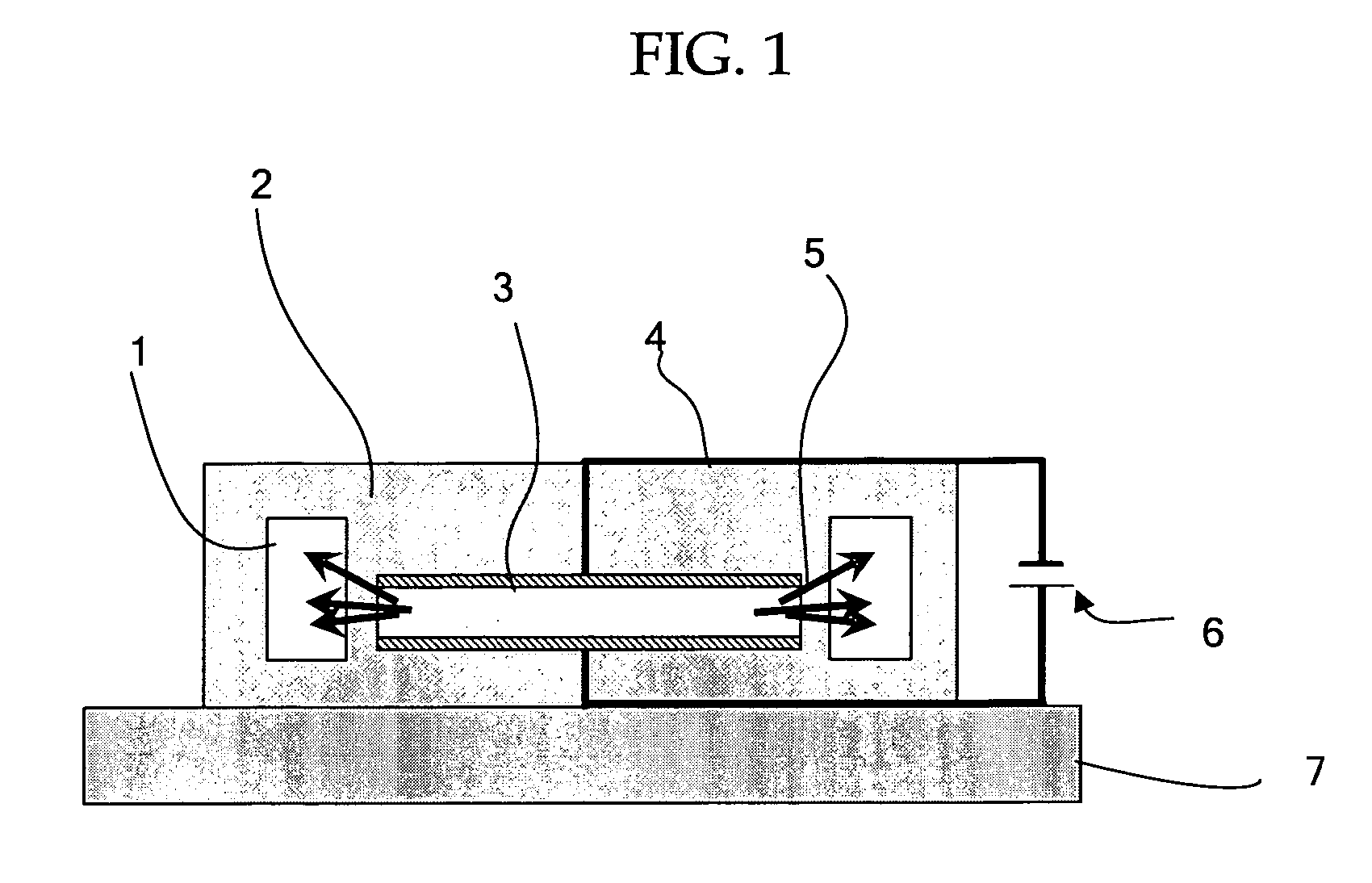
[0013]In a light emitting apparatus of the present invention, the EL emitting unit generates an electroluminescent (EL) light in the light emitting layer. That is, the EL emitting unit functions as an EL element. The EL light generated in the light emitting layer is blocked by the pair of light blocking layers disposed such that they sandwich the light emitting layer in between; therefore, the light emitting layer does not have to be thickened, and the EL light is radiated efficiently from the end (outer periphery) of the light emitting layer regardless of the thickness of the light emitting layer. On one hand, only about 20% of the EL light is radiated from the layer surface of the light emitting layer when the EL light generated in the light emitting layer is radiated from the layer surface. On the other hand, about 80% of the EL light is radiated from the end (outer periphery) of the light emitting layer when the EL light is radiated from the end (outer periphery) of the light emitting layer, and moreover, the 20% of the EL light radiated originally from the layer surface of the light emitting layer is radiated from the end (outer periphery) of the light emitting layer; as a result, about 100% of the EL light is radiated from the end (outer periphery) of the light emitting layer. The light emitting apparatus can utilize about 100% of the EL light and thus have high light utilization efficiency. Also, the EL light radiated from the end (outer periphery) of the light emitting layer is optically guided by the light emitting unit and emitted as it is or as a light modulated to have a wavelength different from that of the EL light. As a result, the light emitting apparatus can emit a light having the wavelength equal to or different from that of the EL light as a linear beam or a laser beam.
[0014]A light emitting apparatus of the present invention preferably has an aspect that the light emitting unit is equipped with an optical guiding member which optically guides the EL light radiated from the end of the light emitting layer. The optical guiding member equipped in the light emitting apparatus can suppress or reduce various losses, e.g. connection loss and transmission loss, or attenuations. When the optical guiding member is designed in the form of a linear waveguide, the excitation density of the light emitted from the light emitting unit may be adjusted to the desired value by adjusting the size (area) of the light emitting layer of the EL emitting unit (EL element), and thus it is possible to increase sufficiently the excitation density. In other words, the luminous energy is proportional to the square of the radius of the EL emitting unit while the density of the driving current in the EL emitting unit is constant and directly proportional to the size (area) of the light emitting layer of the EL emitting unit. On the other hand, since the length of the linear waveguide located opposite to the EL emitting unit, i.e. located surrounding the EL emitting unit, is directly proportional to the radius of the EL emitting unit. Therefore, the increase in the size (area) of the light emitting layer in the EL emitting unit monotonously increases the excitation density in the linear waveguide. As a result, the adjustment of the size (area) of the light emitting layer in the EL emitting unit can turn the light emitted from the light emitting apparatus into a laser beam, i.e. provide a laser oscillation.
[0015]In addition, a light emitting apparatus of the present invention preferably has an aspect that the light emitting unit is equipped with an optical guiding part which optically guides the EL light and a non-optical guiding part which does not optically guides the EL light and that the optical guiding part includes a light emitting material which absorbs the EL light radiated from the light emitting layer and emits a light. In the light emitting apparatus, the light emitting material of the optical guiding part absorbs the EL light and transits to an excited state, and it emits a light when it returns to the ground state (the EL light is modulated or amplified to a light having a different wavelength from that of the EL light). Therefore, an emission of a light having a different wavelength from that of the EL light to the exterior is induced, and the resulting light has superior intensity and luminous energy. Here, the increase in the electric current injected in the light emitting layer in the EL emitting unit (EL element) increase the luminous intensity and the luminous energy of the EL light generated in the light emitting layer, and this increase in the luminous intensity and the luminous energy of the EL light increases the excitation density of the light emitting material as well. When the excitation density of the light emitting material exceeds its threshold, the laser oscillation occurs, and a laser beam is emitted from the light emitting apparatus.
[0017]Furthermore, a light emitting apparatus of the present invention preferably has an aspect that the refractive index of the non-optical guiding part is smaller than the refractive index of the optical guiding part. In the light emitting apparatus, the refractive index difference between the optical guiding part and the non-optical guiding part prevents the EL light, which is likely to leak out to the exterior from the periphery, from entering the non-optical guiding part; the EL light is reflected at the boundary between the optical guiding part and the non-optical guiding part, and it proceeds within the optical guiding part. Therefore, the optical guiding part serves as an optical waveguide, effectively suppressing the leak of the light proceeding in the optical guiding part to the exterior as well as reducing or suppressing the loss of the light guided into the optical guiding part, e.g. transmission loss, or attenuations, and it can emit a light with large luminous intensity.
[0018]Also, a light emitting apparatus of the present invention preferably has the optical guiding part arranged near the periphery of the light emitting layer. In the light emitting apparatus, the EL light emitted from the end (outer periphery) of the light emitting layer is efficiently guided into the optical guiding member without causing losses, e.g. transmission loss, or attenuations.
[0019]Also, in a light emitting apparatus of the present invention, the optical guiding member preferably includes a light reflecting member near the periphery of the optical guiding part which reflects the EL light, emitted from the light emitting layer and transmitted in the optical guiding member, towards the optical guiding part. In the light emitting apparatus, a part of the EL light emitted from the end (outer periphery) of the light emitting layer is transmitted in the optical guiding part without being taken in the optical guiding part and reflected toward the optical guiding part. Therefore, the EL light emitted from the end (outer periphery) of the light emitting layer is efficiently guided by the optical guiding part without causing the losses, e.g. transmission loss, or attenuations.

Problems solved by technology

However, the inorganic semiconductor laser has various problems.
For example, the inorganic semiconductor laser is expensive.
Also, the apparatus thereof is large in size, and the modulation is not easy.
Moreover, since the wavelength of a laser beam is specified by the types of the semiconductor materials, a laser beam having an arbitrary wavelength cannot be obtained, and the applications are limited.
Therefore, the apparatus has a problem that a laser oscillation cannot be provided.
For these increases, the charge transport properties of the hole transport layer and the electron transport layer should be significantly improved, but it is difficult to find such hole transport layer materials and electron transport layer materials.
Also, the proposal of this organic semiconductor laser does not disclose a light guiding method of the EL light extracted from the light emitting layer.
Therefore, the organic semiconductor laser is not guaranteed for the practical performance and thus cannot be used as an apparatus with the performance equal or superior to that of a conventional laser apparatus.
This apparatus uses a semiconductor laser as a light source, and thus it has various problems as mentioned above.
That is, the apparatus is expensive and large in size, and the application is limited because the wavelength of a laser beam is specified by the types of the semiconductor materials and a laser beam at an arbitrary wavelength cannot be obtained.

Method used


Image

  • Light emitting apparatus and light emitting method
  • Light emitting apparatus and light emitting method
  • Light emitting apparatus and light emitting method

Examples


Embodiment Construction

Light Emitting Apparatus and Light Emitting Method

[0028]A light emitting apparatus of the present invention includes an EL emitting unit, a light emitting unit and other units appropriately selected according to requirements.

[0029]A light emitting method of the present invention includes an EL emitting process and a light emitting process, and it further includes other processes appropriately selected according to requirements. The EL emitting process may be favorably performed by means of the EL emitting unit; the light emitting process may be favorably performed by means of the light emitting unit; and the other processes may be favorably performed by means of the other units. Therefore, the light emitting method of the present invention may be favorably performed by means of the light emitting apparatus of the present invention, and the operation of the light emitting apparatus of the present invention is equivalent to the performance of the light emitting method of the present i...


PUM


Abstract

A light emitting apparatus of the present invention includes: an EL emitting unit including at least a light emitting layer which generates an EL light; and a pair of light blocking layers arranged such that they sandwich the light emitting layer so that the layers block the EL light generated in the light emitting layer and that the EL light is radiated only from the end of the light emitting layer; and a light emitting unit which optically guides the EL light radiated from the end of the light emitting layer and emits a light having a wavelength equal to or different from that of the EL light. The EL light is emitted only from the end of the light emitting layer since the EL light generated in the light emitting layer is blocked by the pair of light blocking layers. This emitted EL light is optically guided by the light emitting unit and emitted as it is or a light having a different wavelength from the EL light.

Description

BACKGROUND OF THE INVENTION[0001]1. Field of the Invention[0002]The present invention relates to an optical waveguide light emitting apparatus and light emitting method which employ an electroluminescent (EL) emission as a light source and can emit the EL light or EL-oriented light as a linear beam or a laser beam.[0003]2. Description of the Related Art[0004]Conventionally, linear beams have been heavily used, and among the linear beams, a laser beam has been favorably used in various areas since it is a highly directional coherent light with a sharp spectrum width. For example, a diode laser apparatus which employs a solid laser of an inorganic semiconductor such as GaAs, i.e. semiconductor laser, is widely known as an emitting apparatus of the laser beam. In general, the diode laser apparatus uses a light emission induced by a recombination of injected electrons and holes at a laser cavity, and it is mandatory for the use to satisfy the both electric conditions, e.g. potential dro...

Claims


Application Information

Patent Timeline
Patent Type & Authority Patents(United States)
IPC IPC(8): H05B33/00
CPCG02B6/02033G02B6/10H01S3/0632H01S3/083H01S3/0915H01S3/0933H10K50/856H10K2102/3035
Inventor SOTOYAMA, WATARU
Owner UDC IRELAND
Learn More