
Multistage tuning-tolerant equalizer filter with improved detection mechanisms for lower and higher frequency gain loops

a detection mechanism and equalizer filter technology, applied in the field of data communication, can solve the problems of not being suited for low voltage operation nor small chip area implementation, making multiple tuning signals in circuitry using many comparators, etc., and achieve the effect of improving detection mechanisms and high frequency attenuation behaviour

Inactive Publication Date: 2009-12-15
VRIJE UNIV BRUSSEL
View PDF4 Cites 21 Cited by
  • Summary
  • Abstract
  • Description
  • Claims
  • Application Information

AI Technical Summary

Benefits of technology

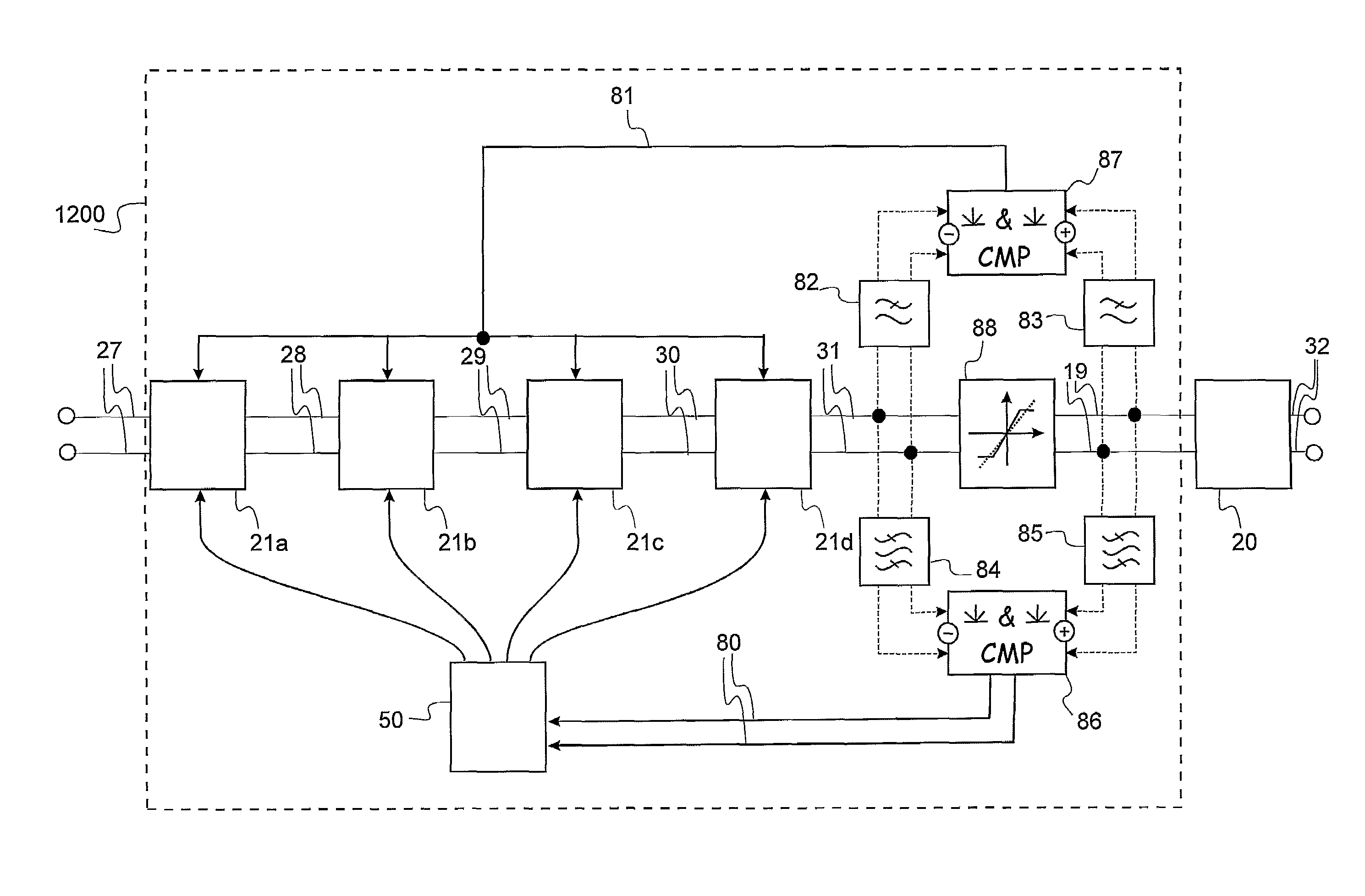
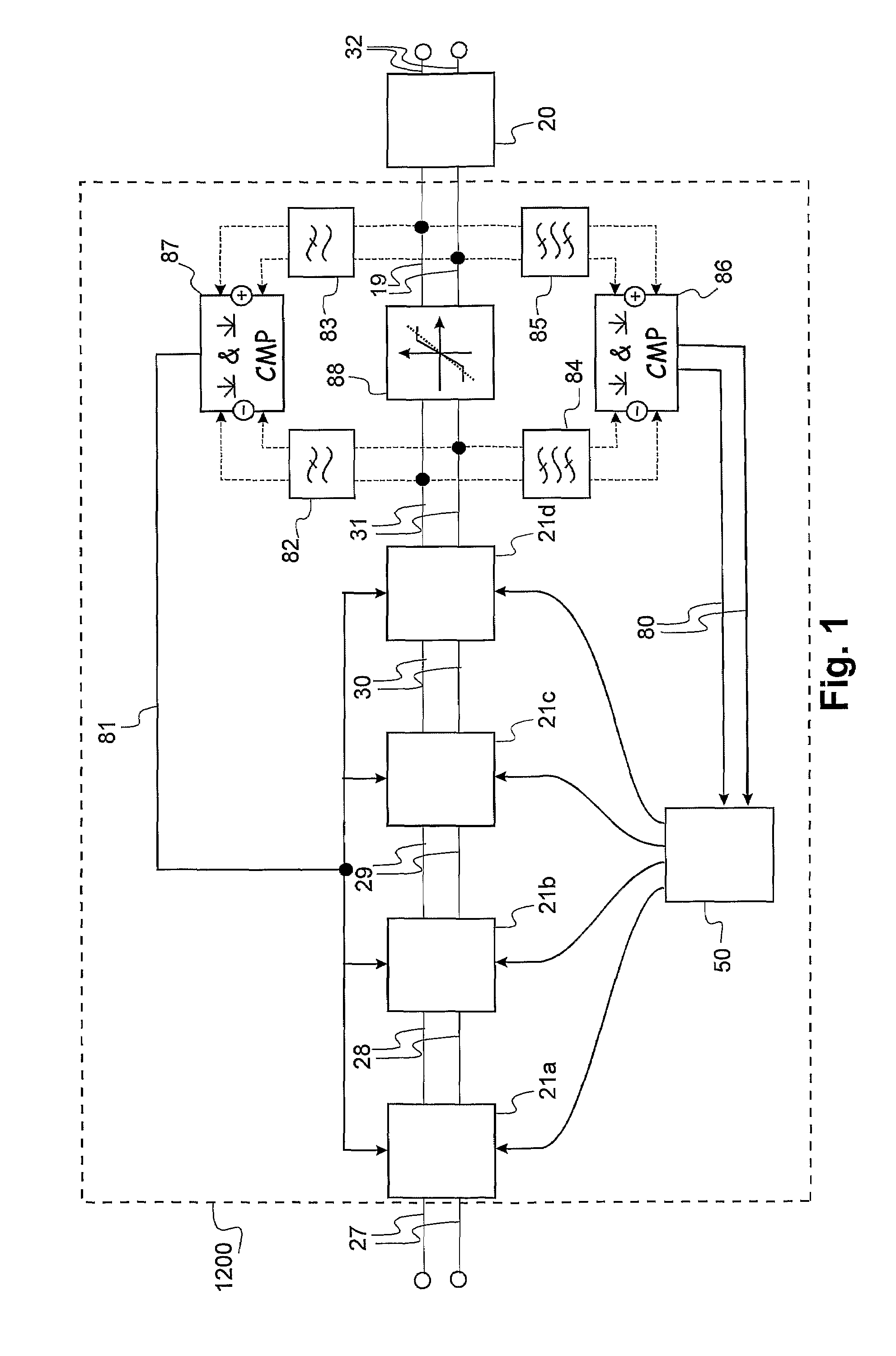
The present invention provides an improved frequency gain loop detection mechanism in equalizer filters. This is achieved by using a comparator circuit that delivers a higher current when the input and output signals of the limiting amplifier are maximally different. The comparator circuit includes a bias current source that delivers a variable current. The gain control means includes a current source delivering a current so low that the high frequency common mode rejection is deteriorated. The equalizer filter comprises at least one amplifying compensation stage with a gain and a saturation level. The gain control means controls the gain of the amplifying compensation stage such that the amplitude of the received signal remains below the saturation level. The invention allows for improved detection of frequency dependent signal modifications introduced by a transmission channel or any other means.

Problems solved by technology

This known method makes multiple tuning signals in circuitry using many comparators and is relatively complex.
It is not suited for low voltage operation nor for implementation on a small chip area using small transistors that have large input offset mismatches.

Method used


Image

  • Multistage tuning-tolerant equalizer filter with improved detection mechanisms for lower and higher frequency gain loops
  • Multistage tuning-tolerant equalizer filter with improved detection mechanisms for lower and higher frequency gain loops
  • Multistage tuning-tolerant equalizer filter with improved detection mechanisms for lower and higher frequency gain loops

Examples


Embodiment Construction

[0050]The present invention will be described with respect to particular embodiments and with reference to certain drawings but the invention is not limited thereto but only by the claims. The drawings described are only schematic and are non-limiting. In the drawings, the size of some of the elements may be exaggerated and not drawn on scale for illustrative purposes. The dimensions and the relative dimensions do not correspond to actual reductions to practice of the invention.

[0051]It is to be noticed that the term “comprising”, used in the claims, should not be interpreted as being restricted to the means listed thereafter. Thus, the scope of the expression “a device comprising means A and B” should not be limited to devices consisting only of components A and B. It means that with respect to the present invention, the only relevant components of the device are A and B.

[0052]Similarly, it is to be noticed that the term “coupled” should not be interpreted as being restricted to di...


PUM


Abstract

The present invention provides an equalizer filter for compensating a received distorted signal for frequency dependent signal modifications introduced by a transmission channel, the received signal having an amplitude. The filter comprises at least one amplifying compensation stage having a gain and a saturation level, at least one limiting amplifier, and gain control means for controlling the gain of the at least one amplifying compensation stage, the gain control means comprising at least one comparator circuit comparing filtered input and output signals of the limiting amplifier, the at least one comparator circuit comprising a bias current source. The bias current source is adapted to deliver a variable current.

Description

TECHNICAL FIELD OF THE INVENTION[0001]The present invention relates to the field of data communication. More particularly, the present invention relates to devices and corresponding methods for multistage equalizer filtering in a line equalizer system, which restore the attenuated signals transmitted over a communication or transmission channel for a wide variety of communication or transmission channels with an acceptable amount of jitter. The present invention also relates to the use of the equaliser in communications system, e.g. in a modem.BACKGROUND OF THE INVENTION[0002]An equalizer system in general compensates frequency dependent losses that a signal experiences when passing through a transmission channel. Transmission channels include, but are not limited to, a wire, a pair of wires, an optical fibre, the reading and writing channels of a storage device like a hard-disc or optical disc, a wireless connection such as a point-to-point or diffuse infra-red or radio connection....

Claims


Application Information

Patent Timeline
Patent Type & Authority Patents(United States)
IPC IPC(8): H03H7/30H03F3/45
CPCH04L25/03878
Inventor KUIJK, MAARTENMAILLARD, XAVIERVAN DEN BRANDE, KOEN
Owner VRIJE UNIV BRUSSEL
Learn More