
Separation and axial ejection of ions based on m/z ratio

a technology of axial ejection and separation of ions, which is applied in the direction of isotope separation, separation process, electric discharge tube, etc., can solve the problems of adversely affecting ion transmission efficiency, poor homogeneity of dc potential, and complicated operation of transfer optics in mass spectrometers, etc., to achieve good m/z separation, increase ion storage capacity, and great ion selectivity

Active Publication Date: 2009-12-15
THERMO FINNIGAN
View PDF26 Cites 8 Cited by
  • Summary
  • Abstract
  • Description
  • Claims
  • Application Information

AI Technical Summary

Benefits of technology

The present invention provides a mechanism and method for manipulating ions in a multipole, which can increase ion storage capacity while maintaining good m / z separation. The invention allows for controlled spreading and movement of ions in samples with large ranges of m / z. It also enables mass selective ejection of ions and reduces interference with other ions. The invention can be used in various mass analyzer systems, such as ion trap, FT system, or hybrid system. Overall, the invention improves the efficiency and accuracy of ion analysis and separation.

Problems solved by technology

The implementation of auxiliary rods in RF-only multipoles may complicate the operation of transfer optics in mass spectrometers.
A notable operationally significant challenge is that the DC potential in the radial plane orthogonal to the major longitudinal axis of the multipole may vary significantly with angular and radial position, being dependent upon the geometry of both rod sets and the differences in DC voltages applied.
Poor homogeneity of DC potential may adversely affect ion transmission efficiency because of high order (such as octopole) DC fields, especially when large excursion of ion trajectories from the major longitudinal axis occurs.

Method used


Image

  • Separation and axial ejection of ions based on m/z ratio
  • Separation and axial ejection of ions based on m/z ratio
  • Separation and axial ejection of ions based on m/z ratio

Examples


Embodiment Construction

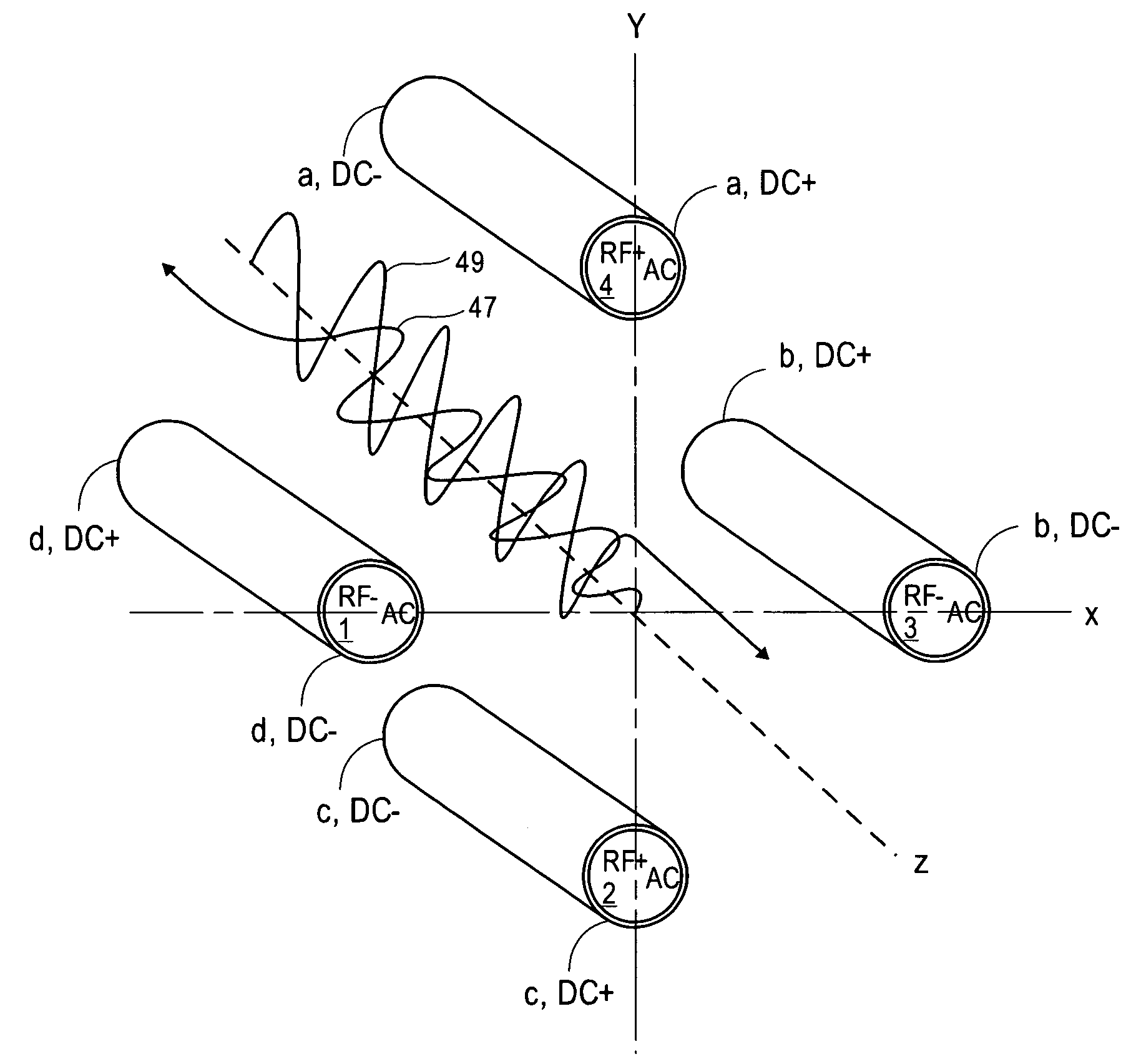
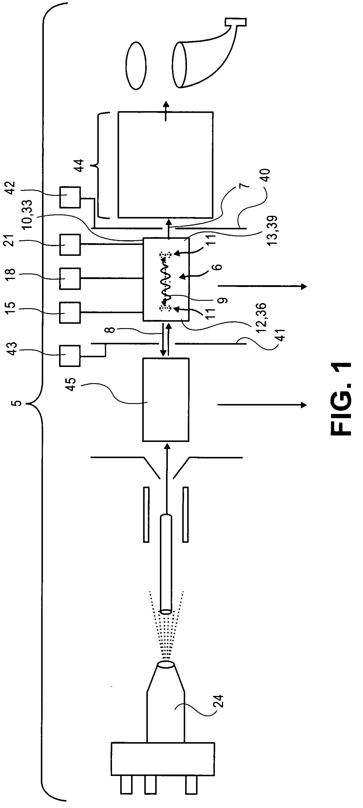
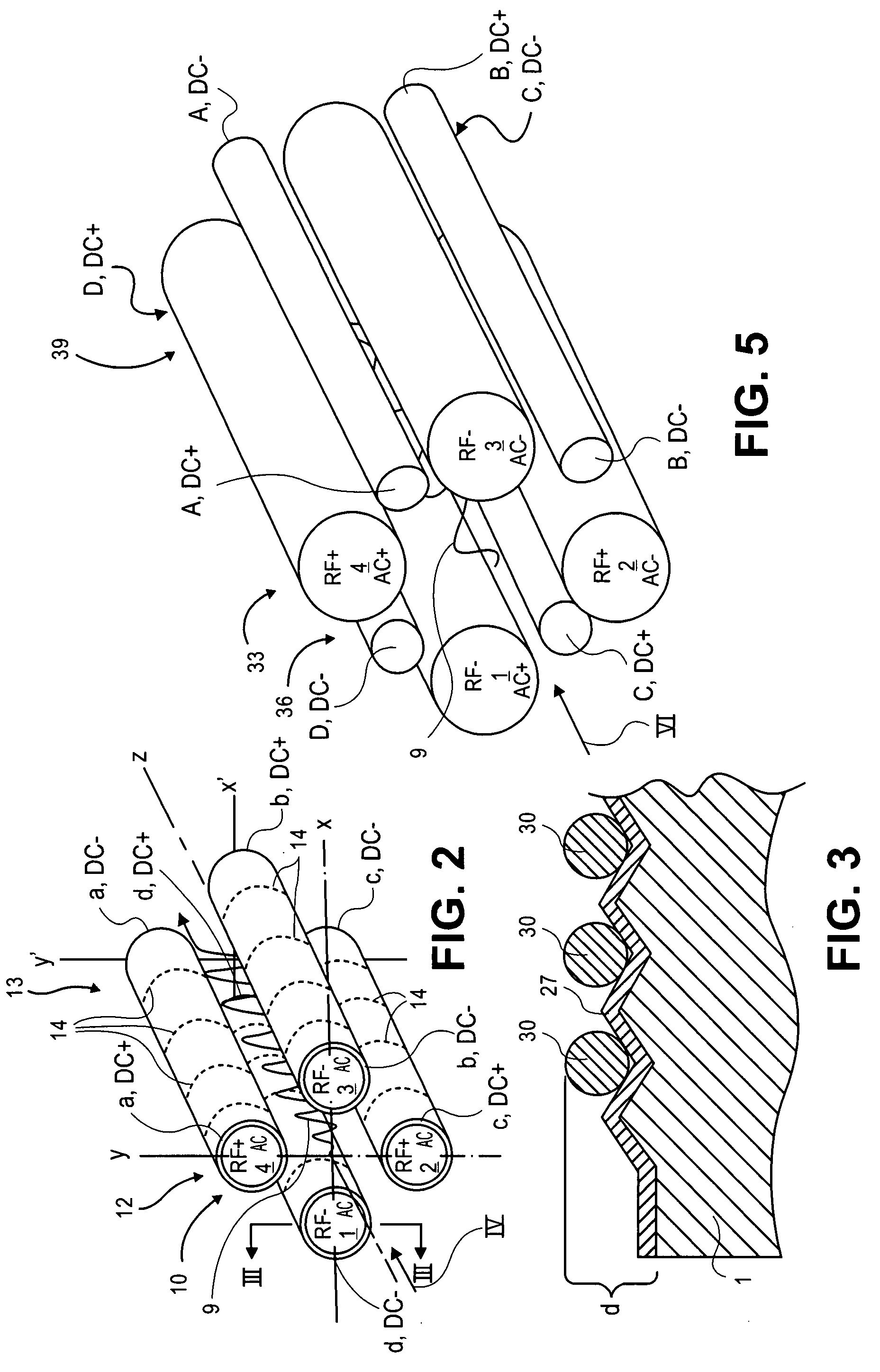
[0046]Multipole devices are filled with ions to be analyzed. The ions are permitted to spread along a length of the multipole. Collision cooling may be applied at one or more positions along a length of the multipole. When barriers are placed upstream and downstream of the multipole, collisional cooling results in the ions generally moving axially toward a center of the multipole. Additional potential wells may be incorporated by selecting potentials for segments along a length of rod electrodes of the multipole, for example. A main RF voltage is applied to the multipole to confine the ions radially and urge them to reside on a center line or central axis of the multipole. An auxiliary RF or excitation voltage (denoted as AC in the Figures) may be applied and together with the main RF may excite ions of a preselected m / z off the central axis. This excitation has typically been done by moving the preselected ions of a desired m / z into fringing fields near ends of the multipole. One o...


PUM


Abstract

A mass spectrometer includes a multipole having a main RF field for radially containing ions generally on a central axis. The multipole has first and second axial DC fields in opposite first and second direction along a length of the multipole. The first and second axial DC fields approach or add substantially to zero on the central axis. The multipole has an excitation voltage applied thereto for selectively exciting the ions of desired m / z ratios off the central axis. The excitation voltage thus causes excursion of the ions into a region where either the first or second axial DC field is strong. Thus, excitation of the ions and the DC fields cause ion drift toward a front end or a back end of the multipole. Further excitation moves the ions into regions of the DC fields that overcome barriers and causes axial ejection of the ions from the multipole.

Description

FIELD OF THE INVENTION[0001]The present invention relates generally to multipole devices used as ion traps or for storage and separation of ions in a mass spectrometer, and more specifically to such a multipole configured for selective axial ejection of ions.BACKGROUND OF THE INVENTION[0002]As will be shown and described below, the storage and separation in accordance with the present invention may be applied in any of a variety of multipoles that function as collision cells or ion traps. One example of a multipole in which the embodiments of the present invention may be applied is an RF-only multipole. RF-only multipole structures are widely used in mass spectrometers as ion guides and / or collision cells. Generally described, RF-only multipoles consist of four or more elongated rods that bound an interior region through which ions are transmitted. The ions enter and exit the multipole rod set axially. A radio-frequency (RF) voltage is applied to opposed rod pairs to generate an RF ...

Claims


Application Information

Patent Timeline
Patent Type & Authority Patents(United States)
IPC IPC(8): B01D59/44H01J49/00
CPCH01J49/427
Inventor KOVTOUN, VIATCHESLAV V.
Owner THERMO FINNIGAN
Learn More