
Steam generator in horizontal constructional form

a generator and horizontal construction technology, applied in the direction of steam generation using hot heat carriers, steam separation arrangements, ignition automatic control, etc., can solve the problems of limited operational flexibility, water-steam mixture problems in the evaporating tube, and limited through-feed of these cyclone separators with water, so as to achieve reliable water separation and high operational flexibility

Active Publication Date: 2009-12-08
SIEMENS ENERGY GLOBAL GMBH & CO KG
View PDF15 Cites 11 Cited by
  • Summary
  • Abstract
  • Description
  • Claims
  • Application Information

AI Technical Summary

Benefits of technology

[0009]The invention, therefore, is based on the object of disclosing a once-through steam generator of the aforementioned type, which with minimized production cost also enables an especially high operational flexibility in starting mode or low load mode, and consequently especially also enables minimized starting and load change times.
[0020]An especially high operational stability of the steam generator is achievable by the evaporative once-through heating surface being designed for a self-stabilizing flow behavior when heating differences occur between individual steam generator tubes of the once-through heating surface. This is achievable by the evaporative once-through heating surface being designed in an especially advantageous development in such a way that one steam generator tube, which is heated more in comparison to a further steam generator tube of the same once-through heating surface, has a higher throughput of flow medium in comparison to the further steam generator tube. The evaporative once-through heating surface which is designed in such a way, therefore, demonstrates in the fashion of the flow characteristic of a natural recirculating evaporative heating surface (natural recirculating characteristic) a self-stabilizing behavior when different heating of individual steam generator tubes occurs, which behavior, without the need of external exertion of influence, also leads to an adjustment of the temperatures on the outlet side on differently heated steam generator tubes which are connected in parallel on the flow medium side.
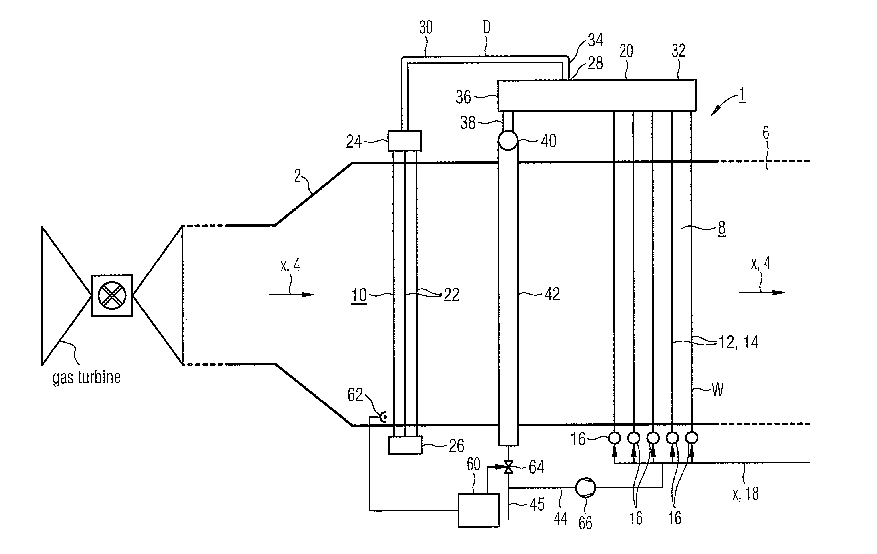
[0022]The advantages which are achieved by the invention are especially that a decentrally designed water separating system can be made available by means of the integration of the water separating function in the outlet headers, in which on account of the small number of superheater tubes which are connected downstream to each individual water separator, a costly distribution system can be dispensed with. Consequently, a through-feed of unevaporated flow medium by means of the water separators is also possible, so that the evaporation end point can be shifted into the superheater tubes when required. Consequently, especially large portions of the heating surfaces are usable for evaporation purposes, particularly in starting mode and low load mode, wherein, moreover, an especially high operational flexibility is also achievable in these load states. Especially by means of the T-piece-like design of the outlet header as a cylindrical body with a branching outflow pipe section, moreover, a reliable water separation according to the principle of inertia separation can be achieved by simple means.

Problems solved by technology

In other words, during this operating mode a water-steam mixture issues from the evaporating tubes.
However, a distribution of such a water-steam mixture to superheater tubes, which customarily are connected downstream to the evaporating tubes, as a rule is not possible in the once-through steam generator; the distribution which is customarily provided rather presupposes that the flow medium which is to be distributed exclusively contains steam portions.
For design-related reasons, a through-feed of these cyclone separators with water is only possible to a limited degree.
The heating surface which is usable for evaporation, therefore, has to lie upstream of the separators, as seen in the flow direction of the flow medium, and so is limited.
The limitation of the operational flexibility which is associated with these aspects, in addition to the high equipment cost, customarily as a rule gives rise to undesirably long starting times and reaction times during load changes of the once-through steam generator in low load mode.

Method used


Image

  • Steam generator in horizontal constructional form
  • Steam generator in horizontal constructional form

Examples


Embodiment Construction

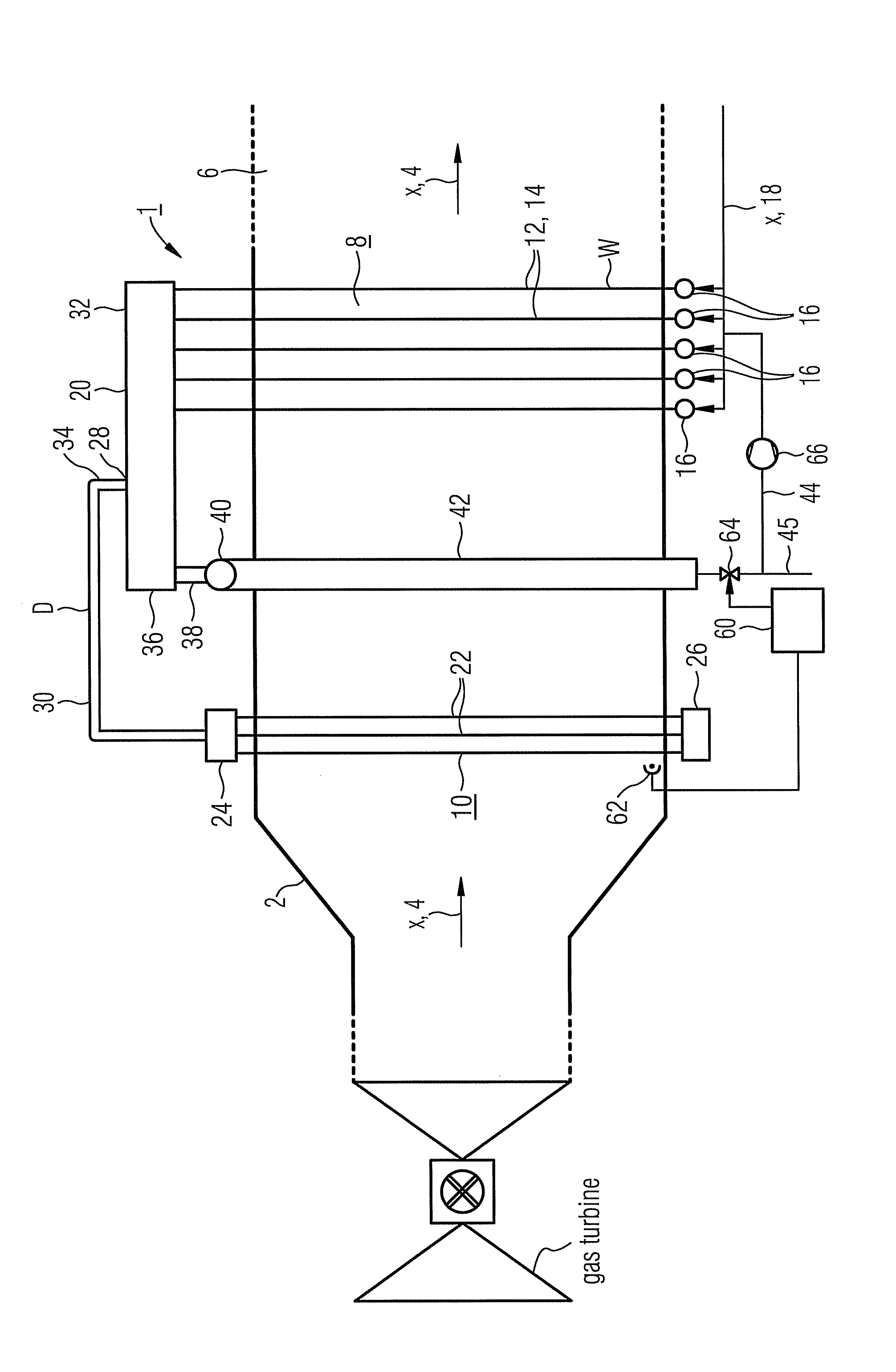
[0024]The steam generator 1, which is shown in the FIGURE with its evaporative section, in the fashion of a heat recovery steam generator is connected downstream on the exhaust gas side to a gas turbine, which is not shown in detail. The steam generator 1 has a circumferential wall 2, which forms a hot gas passage 6 for the exhaust gas from the gas turbine, which hot gas passage is exposed to through-flow in an approximately horizontal hot gas direction x which is indicated by arrows 4. An evaporative once-through heating surface 8, which is designed according to the once-through principle, is arranged in the hot gas passage 6 and to which a superheater heating surface 10 is connected downstream for through-flow of a flow medium W, D.

[0025]The evaporative once-through heating surface 8 is subjectable to admission of unevaporated flow medium W, which in normal load mode or full load mode is evaporated during the once-through passage by means of the evaporative once-through heating su...


PUM


Abstract

The invention relates to a steam generator whose continuously heating evaporator surface is arranged in a hot gas channel for a hot gas passage in a substantially horizontal direction and which comprises a plurality of steam generating pipes passed through by flowing medium, wherein a plurality of output collectors which are mounted downstream of certain steam generating pipes, on the side of flowing medium, are oriented in the longitudinal direction thereof substantially parallel to the hot gas direction. The invention improves the steam generator such that it is possible to attain a high operational flexibility, a particularly reduced start- and load-alternation time, including starting operation or light load phases and to maintain a low-cost production. Each output collector comprises an integrated water separating element by means of which said collector is connected, on the side of flowing medium, to a plurality of downstream arranged overheating pipes of an overheating surface.

Description

CROSS REFERENCE TO RELATED APPLICATIONS[0001]This application is the US National Stage of International Application No. PCT / EP2006 / 050851, filed Feb. 10, 2006 and claims the benefit thereof. The International Application claims the benefits of European application No. 05003268.9 filed Feb. 16, 2005, both of the applications are incorporated by reference herein in their entirety.FIELD OF INVENTION[0002]The invention refers to a steam generator, in which an evaporative once-through heating surface is arranged in a hot gas passage which is exposable to through-flow in an approximately horizontal hot gas direction, which evaporative once-through heating surface comprises a number of steam generator tubes which are connected parallel to the through-flow of a flow medium, with a number of outlet headers which are connected downstream on the flow medium side to some steam generator tubes.BACKGROUND OF THE INVENTION[0003]In a gas and steam turbine plant, the heat which is contained in the e...

Claims


Application Information

Patent Timeline
Patent Type & Authority Patents(United States)
IPC IPC(8): F22B1/18
CPCF22B37/26F22B1/1815
Inventor BRUCKNER, JANFRANKE, JOACHIMKRAL, RUDOLF
Owner SIEMENS ENERGY GLOBAL GMBH & CO KG
Learn More