
Enhanced sole assembly with offset hole

a technology of offset hole and sole, which is applied in the direction of footwear, applications, footwear, etc., can solve the problems of excessive rolling inward, underdeveloped arches may suffer from overpronation, and the foot may not pronate enough, so as to facilitate the natural transition of impact and propulsion forces

Inactive Publication Date: 2009-12-08
FILA LUXEMBOURG S A R L
View PDF27 Cites 19 Cited by
  • Summary
  • Abstract
  • Description
  • Claims
  • Application Information

AI Technical Summary

Benefits of technology

The solution provides enhanced traction, lateral stability, and a natural transition of forces during stride, while reducing the overall height of the sole assembly and minimizing the concentration of heel strike forces, thus improving comfort and performance.

Problems solved by technology

In some cases, the foot may not pronate enough, a condition called “underpronation” or “supination.” Furthermore, persons with underdeveloped arches may suffer from “overpronation,” wherein the foot rolls inward excessively.
Either condition is unhealthy for the foot and can cause shin or joint pain.
Further, these conventional unitary sole designs were heavy and held the foot relatively high above the ground surface, thereby reducing lateral stability.
Based on these characteristics, the footwear industries has perceived the unitary sole to be unsuitable for athletic footwear and has developed alternative designs for performance footwear.
However, the present inventors have recognized that the shank region of the split sole is typically raised from ground contact (particularly along a periphery), which reduces traction capabilities and lateral support in this region of the split sole design.
Further, the arched shank region requires a vertical dimension that increases the overall height of the split sole assembly, thus further reducing lateral stability.
Yet another problem with the split sole is that the discrete heel region of this design generally concentrates heel strike forces in a small area making it more difficult for the wearer to naturally transition heel impact forces to midstance and toe off during stride.
Moreover, the heel counter does nothing to reduce the overall height of the sole assembly, and the thin membrane provides only weak support for wearer's heel and little dispersion of heel impact forces.
Still further, the flexible membrane may be a barrier to ventilation of the foot.
Again, however, these ventilation features have been implemented in non-unitary sole designs.
Moreover, passages that extend from the bottom of the outsole can function as suction cups on the outsole, thus causing additional resistance to lifting the foot, especially in wet or muddy areas.
While side surface air passages are also known, these passages typically extend only from a lateral to medial side of the sole assembly, thus providing no ventilation to the interior of the shoe.

Method used


Image

  • Enhanced sole assembly with offset hole
  • Enhanced sole assembly with offset hole
  • Enhanced sole assembly with offset hole

Examples


first embodiment

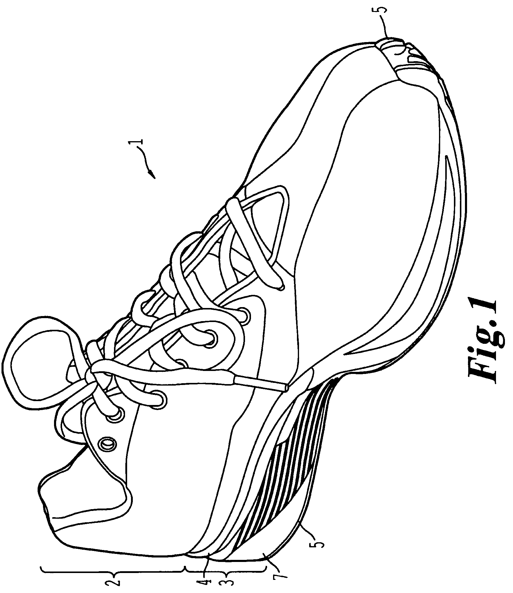
[0065]FIG. 6 shows a medial side view of the present invention. As shown in FIG. 6, the unitary midsole 7 has no hole on its medial side. Thus, the location of the lateral side hole 23 softens the lateral side of the sole assembly 3 relative to the medial side, thereby providing an effect similar to an arch support. The amount of support provided can be adjusted by changing the shape or thickness of the heel cradle 4, the hole frame 24, and the shape and size of the lateral side hole 23.

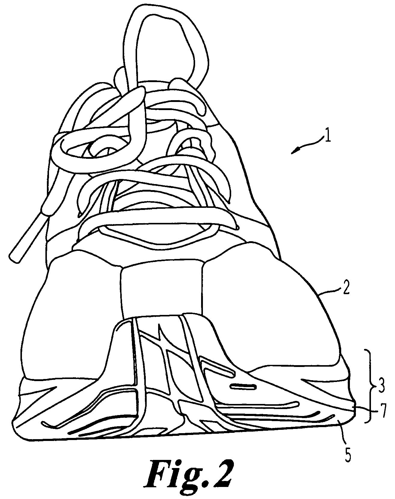
[0066]FIG. 7a depicts a rear view of the first embodiment of the present invention. In FIG. 7a, the heel hole 25 is positioned approximately in the center of the heel region, but with a slight bias toward the lateral side of the shoe. Thus, the heel hole 25 provides a centering effect, while also facilitating proper pronation of the foot by softening the lateral side of the unitary midsole 7, even if no heel cradle is present. If the heel cradle is present, the centering effect of the heel cradle 4 i...

third embodiment

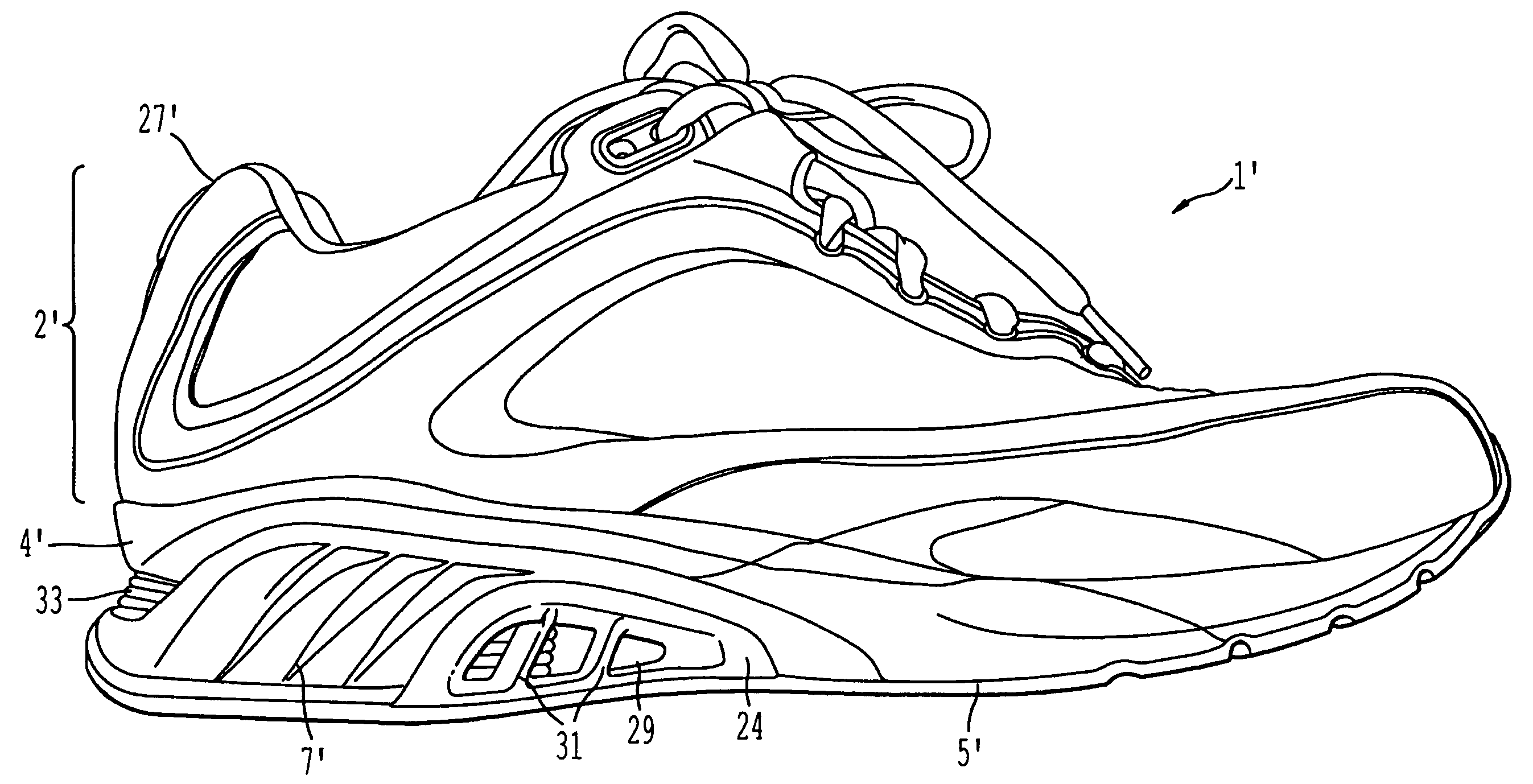
[0075]Unlike the first two embodiments, the unitary midsole 7″ of the third embodiment does not have a lateral hole. The lateral side of the shoe 1″ is best shown in FIG. 19. The lateral hole may be omitted when the wearer has a tendency to underpronate. Thus, without the lateral hole, the lateral side of the unitary midsole 7″ is stiffer and the outside edge of the foot will compress the sole assembly 3″ to a lesser extent.

[0076]FIG. 20 shows the sole assembly 3″ with medial hole 29″ and hole frame 24, but no fins 31. Thus, fins 31 are optional and are included when additional stiffness is required, or to enhance aesthetic appearance. Like the lateral holes described above, the medial holes are in fluid communication with the bottom hole 19. The inclusion of the medial hole 29″ enhances the effect of the exclusion of the lateral hole regarding pronation of the foot. In other words, a sole assembly 3″ with a medial hole 29″, but no lateral hole will typically have a stronger tendenc...


PUM


Abstract

A sole assembly including a midsole made of resilient cushion material and having an upper support surface configured to support a plantar region of a human foot, a lower surface and a sidewall connecting the upper and lower surfaces. An outsole is provided on the lower surface and configured to provide traction with a ground surface. Further, at least one sidewall hole provided in the sidewall and configured to provide ventilation to the foot, wherein the at least one sidewall hole is provided at a predetermined position in the sidewall in order to accommodate a characteristic of the foot.

Description

FIELD OF THE INVENTION[0001]The present invention relates to a device that supports a person's foot, and more specifically, to a sole assembly including an offset through hole in heel portion of the midsole.BACKGROUND OF THE INVENTION[0002]Contemporary shoes provide a complex combination of cushion, traction, and body-fitting elements that facilitate the natural progression of the foot along the ground during wear. When walking or running, the first part of the foot to strike the ground is the heel at the instant of “heelstrike.” Then the foot rolls forward from the heel region, through the midfoot region and the ball of the foot, and finally to the toe region where the foot breaks contact with the ground in a “toe-off” action. In addition to the above-described progression from the heel to the toe, the foot typically rolls from the outside to the inside (lateral side to the medial side), a process called “pronation” which disperses some of the energy generated during the impact of ...

Claims


Application Information

Patent Timeline
Patent Type & Authority Patents(United States)
IPC IPC(8): A43B7/06A43B13/18
CPCA43B7/06A43B13/187A43B13/181A43B7/088
Inventor BREWER, CHRISHENRICHOT, OLIVIER
Owner FILA LUXEMBOURG S A R L
Learn More