
Power supply unit and portable device

a power supply unit and portable device technology, applied in emergency power supply arrangements, instruments, process and machine control, etc., can solve the problems of inevitably consuming a certain amount of current in standby condition, and desirable that the current increase, so as to simplify the structure of a portable device

Active Publication Date: 2009-12-01
ROHM CO LTD
View PDF31 Cites 14 Cited by
  • Summary
  • Abstract
  • Description
  • Claims
  • Application Information

AI Technical Summary

Benefits of technology

[0008]It is, therefore, an object of the present invention to provide a power supply unit capable of executing soft start without increasing its consumption current and having a reduced number of terminals. It is another object of the invention to provide a portable device accommodating such power supply unit.
[0014]According to the invention, the power supply unit can control its own enablement and disablement based on an operation command input voltage inputted into the operation command signal input terminal thereof, and generates a reference voltage and a level shift voltage for executing a soft start. In this arrangement, the power supply unit can undergo a soft start without increasing its consumption current, and the unit may have a reduced number of external terminals, thereby facilitating downsizing of the IC chip that incorporates the power supply unit.
[0016]It should be noted that an operation command signal generated by the control device in the form of, for example, a step-like voltage, rises gradually with a predetermined time constant of the time constant circuit and is supplied to the power supply unit as the operation command input signal. In this way, an operation command input signal can be formed by an additional simple time constant circuit. Thus, the structure of a portable device can be simplified accordingly.

Problems solved by technology

Thus, the conventional power supply unit inevitably consumes a certain amount of current in the standby condition.
Therefore, in order to perform soft start, it is not desirable that the current increases.

Method used


Image

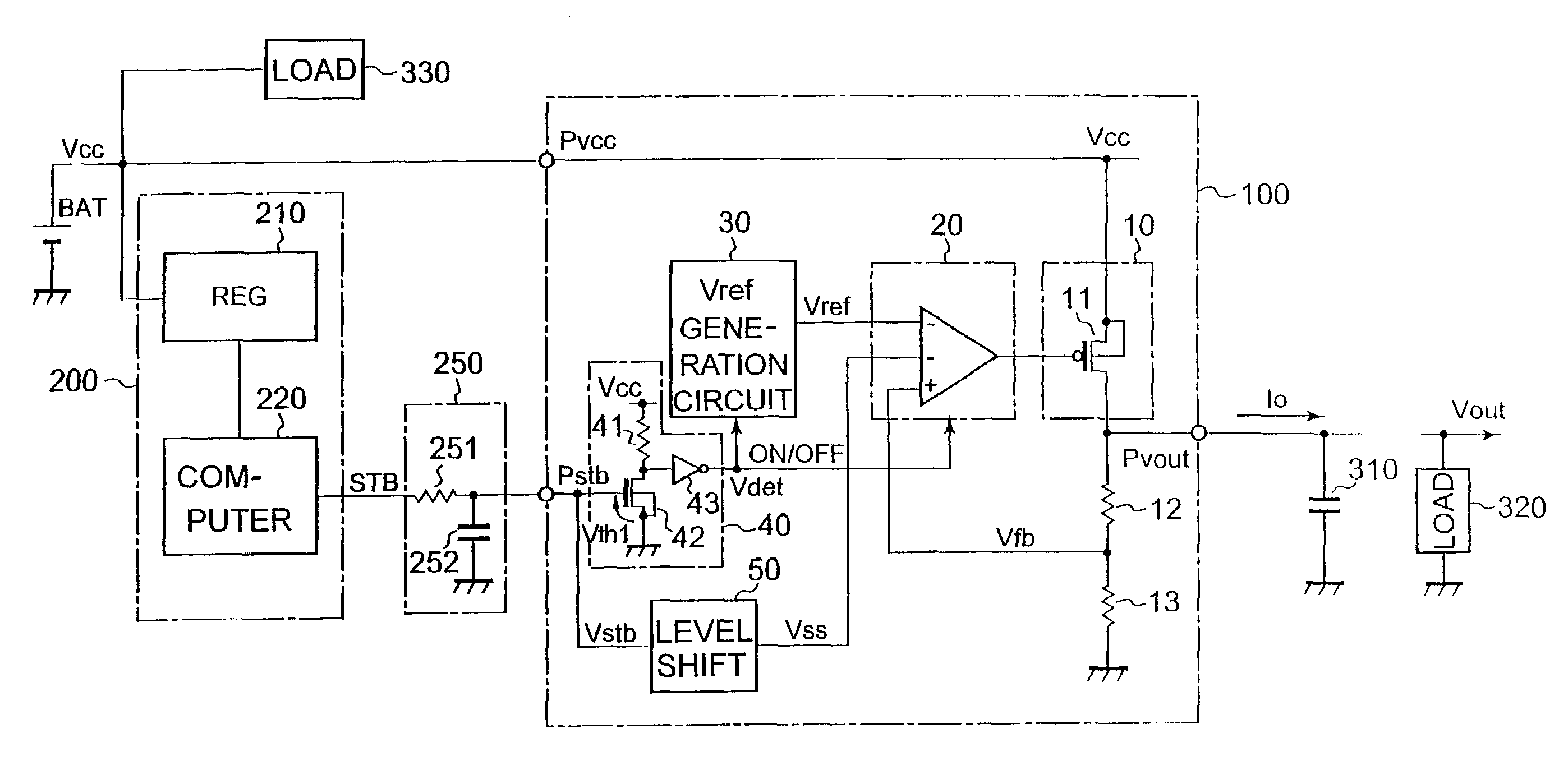
  • Power supply unit and portable device
  • Power supply unit and portable device
  • Power supply unit and portable device

Examples


Embodiment Construction

[0022]The inventive power supply unit and the portable device will now be described in detail with reference to the accompanying drawings. Incidentally, the power supply unit of the invention can be said as a semiconductor device, since it is fabricated in a transistorized LSI.

[0023]Referring to FIG. 1, there is shown an arrangement of the power supply unit in accordance with a first embodiment of the invention, along with an arrangement of the portable device utilizing the power supply unit.

[0024]As shown in FIG. 1, a battery power supply BAT generates a power supply voltage Vcc. The level of the power supply voltage Vcc changes with the charging / discharging condition of the battery power supply BAT.

[0025]This power supply voltage Vcc is inputted into the power supply unit 100 via a power supply voltage input terminal Pvcc. The output circuit 10 is configured in the form of a series regulator that contains an output transistor 11, which provides a predetermined output voltage Vout ...


PUM


Abstract

A step-like operation command signal is inputted into a time-constant circuit to generate a gradually rising operation command input voltage, which is supplied to a power supply unit. Enablement and disablement of the power supply unit is controlled on the basis of the operational command input voltage. When the operation command input voltage exceeds a first predetermined voltage level, a detection signal and a reference voltage are generated, and at the same time an error amplification circuit is enabled. On the other hand, when the operation command input voltage exceeds a second predetermined voltage level, a level shift voltage for initiating a soft start is generated, which enables execution of a soft start of the power supply unit without increasing its consumption current and reduction of the number of its terminals.

Description

BACKGROUND OF THE INVENTION[0001]1. Field of the Invention[0002]This invention relates to an electric power supply unit for providing a predetermined output voltage through conversion of a power supply voltage of a dc power supply such as a battery, and to a portable device equipped with such power supply unit.[0003]2. Description of the Related Art[0004]A power supply unit such as a series regulator typically converts the power supply voltage of a dc power supply to a predetermined output voltage. It is necessary for such power supply unit to suppress inrush current that would otherwise flow into a load and a smoothing capacitor connected to the power supply unit.[0005]A conventional power supply unit can be provided with a capacitor connected in series with a constant current source and a power switch connected in parallel with the capacitor such that when the power switch is turned off (or opened) the constant current can gradually charge the capacitor, thereby causing the power ...

Claims


Application Information

Patent Timeline
Patent Type & Authority Patents(United States)
IPC IPC(8): G05F1/00H02J7/00G05F1/56G05F1/575
CPCG05F1/575Y10S323/901
Inventor HOSHINO, TAICHIKIKUCHI, HIROKI
Owner ROHM CO LTD
Learn More