Flexible thin printed battery and device and method of manufacturing same
a thin battery and printed battery technology, applied in the field of flexible thin battery and device, can solve the problems of low cost per unit application, low conductive performance of lithium-based technologies, and high cost of high-throughput inexpensive manufacturing processes, etc., and achieve the effect of sufficient conductive performan
- Summary
- Abstract
- Description
- Claims
- Application Information
AI Technical Summary
Benefits of technology
Problems solved by technology
Method used
Image
Examples
example 1
All Percents are by Weight Unless Otherwise Indicated
[0119]Cells were made according to this example. The anode ink wet formulation was 9.6 percent zinc acetate dihydrate, 31.7 percent water, 1.3 percent PVP (molecular weight of 2.2 to 2.8 million) and 57.4 percent zinc dust. The zinc ink was made by first combining the zinc acetate dihydrate obtained from Aldrich Chemical Company with water to form an aqueous solution. PVP was added to the aqueous solution to make a viscous salt-polymer solution. Zinc dust added and the mixture was stirred until homogeneous. The zinc dust was leaded with 0.16 percent lead. The zinc dust had a Microtrac average volumetric particle size, or d(50) value of about 10 microns. The mixture was allowed to stand to achieve the appropriate thickness, about 90 to 120 minutes. An anode was then screen printed by hand. The anode substrate was the inner heat sealable surface of a flexible polymer and metal laminate packaging material available from Pharma Center...
example 2
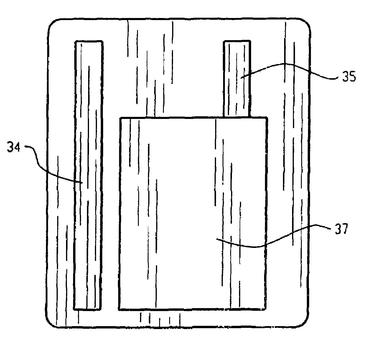
[0124]Co-planar electrode assembly cells were constructed according to this example. An anode was printed using the same anode ink formulation and substrate as in Example 1, and a 0.002 inch thick zinc mesh anode current collector as in Example 1 was affixed to the substrate in the same manner as in Example 1. The anode 34 was screen printed to a size of 50.4 millimeters×6.8 millimeters with an average thickness of 0.109 millimeters. The cathode current collector and cathode were stenciled using the same formulation as in Example 1 onto the same substrate as the anode to form a co-planar electrode arrangement. The cathode current collector 35 was stenciled to a size of 40 millimeters×27 millimeters×0.036 millimeters, while the cathode ink 37 was stenciled onto the current collector with a thickness of 0.166 millimeters. See FIG. 9. The gap between the cathode and the anode was 2.0 millimeters. The electrode surfaces were wetted up with the same electrolyte as in Example 1, and the s...
example 3
[0127]Co-facial electrode assembly cells were constructed as follows. A zinc mesh anode was utilized in the cells of this example, consisting of a 0.005 inch thick piece of zinc mesh available from Delkar Corporation. The mesh was cut to 39 millimeters×37 millimeters and adhered to the same substrate material as in Examples 1 and 2. The anode current collector was formed from this zinc mesh also and adhered to the substrate in the same manner.
[0128]The cathode current collector for the cells of this example used the same carbon ink as in Example 1, and was stenciled as in Example 1 to a size of 40 millimeters×38 millimeters with an average thickness of 0.052 millimeters on the same substrate material as in Example 1. The cathode ink was the same ink formulation as in Example 1, and was stenciled onto the collector as in Example 1 to an average thickness of 0.149 millimeters. The same separator material was used as in Example 1 and the same electrolyte as in Example 1 was introduced ...
PUM
| Property | Measurement | Unit |
|---|---|---|
| Microtrac particle size d | aaaaa | aaaaa |
| closed circuit voltage | aaaaa | aaaaa |
| current | aaaaa | aaaaa |
Abstract
Description
Claims
Application Information
 - R&D
- Intellectual Property
- Life Sciences
- Materials
- Tech Scout
- Unparalleled Data Quality
- Higher Quality Content
- 60% Fewer Hallucinations
Browse by: Latest US Patents, China's latest patents, Technical Efficacy Thesaurus, Application Domain, Technology Topic, Popular Technical Reports.
© 2025 PatSnap. All rights reserved.Legal|Privacy policy|Modern Slavery Act Transparency Statement|Sitemap|About US| Contact US: help@patsnap.com


