
Cooling system and hybrid vehicle including cooling system

a technology of cooling system and hybrid vehicle, which is applied in the direction of refrigeration components, non-pressure vessels, refrigeration machines, etc., can solve the problems of not giving cooling to driving sources which generate a larger amount of heat, and the cooling may become insufficient, so as to achieve the effect of more efficient cooling, more efficient cooling, and more efficient cooling

Inactive Publication Date: 2009-11-24
TOYOTA JIDOSHA KK
View PDF22 Cites 10 Cited by
  • Summary
  • Abstract
  • Description
  • Claims
  • Application Information

AI Technical Summary

Benefits of technology

The invention relates to a cooling system for a moving body, such as a vehicle or a train, that includes multiple heat exchangers. The heat exchangers are arranged in a plane perpendicular to the direction of movement, or in one plane parallel to the direction of movement, at the front of the moving body. This arrangement allows for more efficient cooling and better air conditioning. The cooling system can be installed in a hybrid vehicle, which includes both an air conditioning system for the passenger compartment and a driving source cooling system. Overall, the cooling system improves the performance and efficiency of the air conditioning system and the driving source cooling system in a moving body.

Problems solved by technology

However, in the case of the aforementioned cooling system, consideration is not given to cooling of a driving source which generates a larger amount of heat than an amount of heat generated by the electronic component.
The cooling may become insufficient, depending on a position of the driving source heat exchanger.

Method used


Image

  • Cooling system and hybrid vehicle including cooling system
  • Cooling system and hybrid vehicle including cooling system
  • Cooling system and hybrid vehicle including cooling system

Examples


Embodiment Construction

[0024]Next, an exemplary embodiment of the invention will be described.

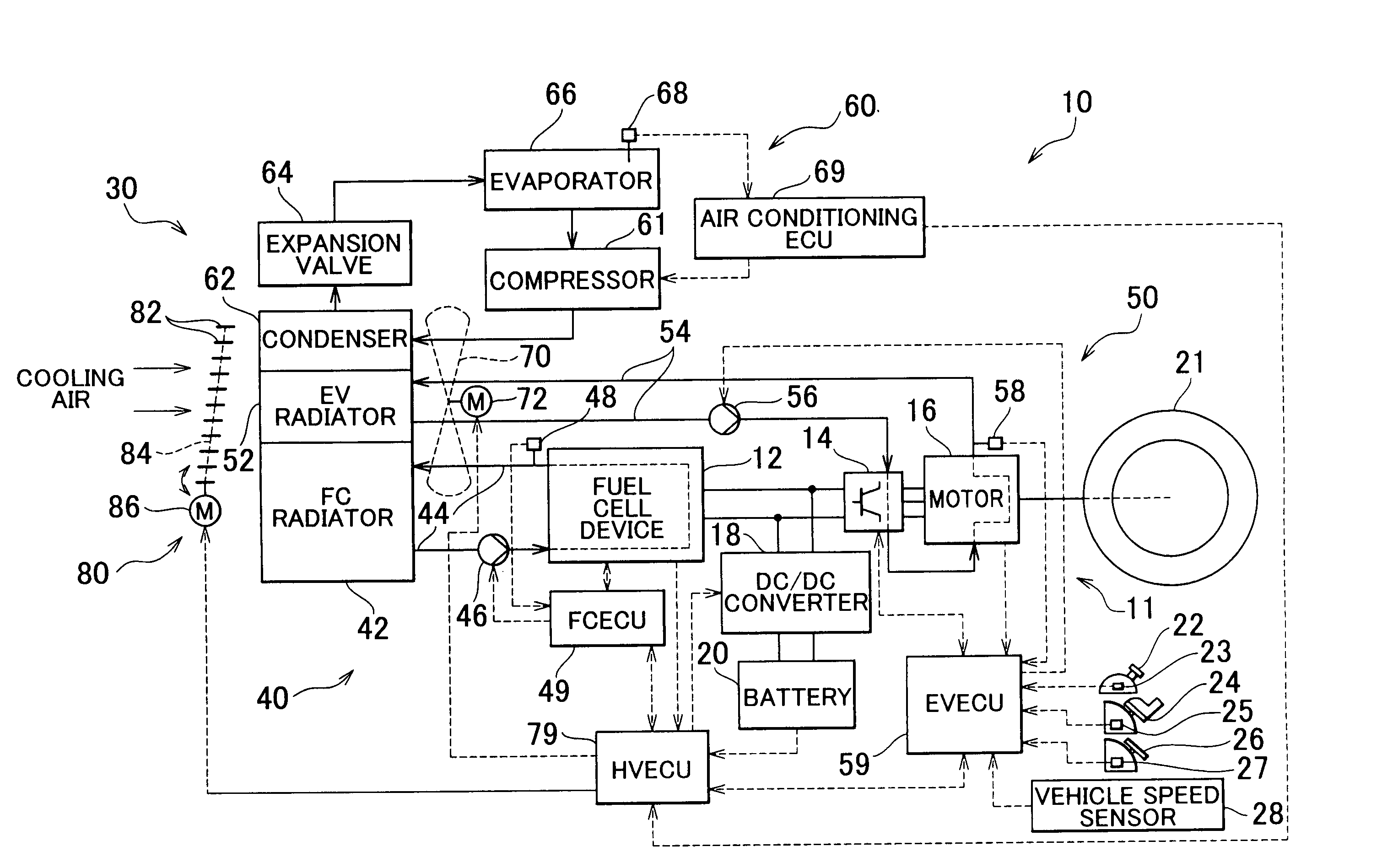
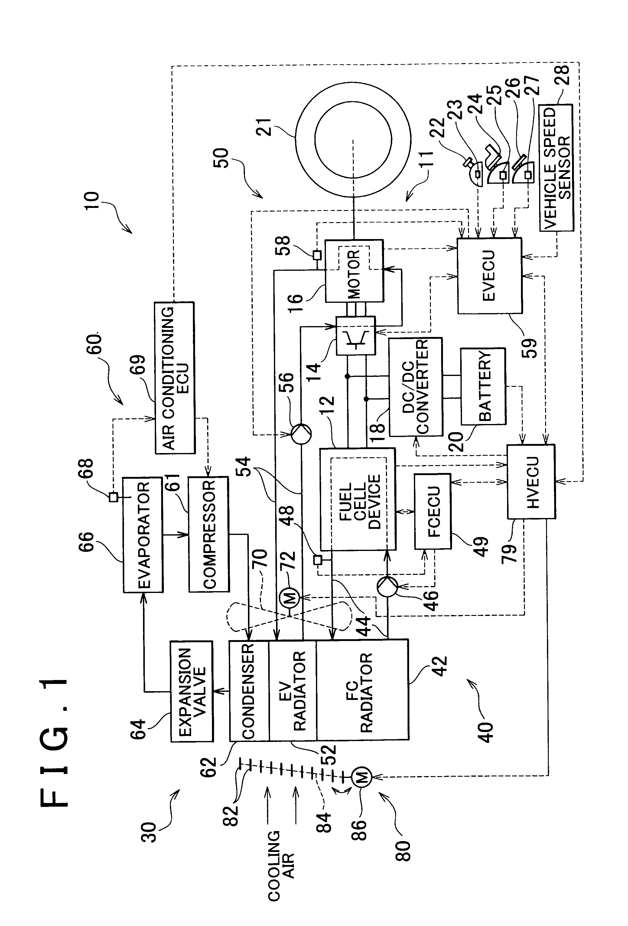
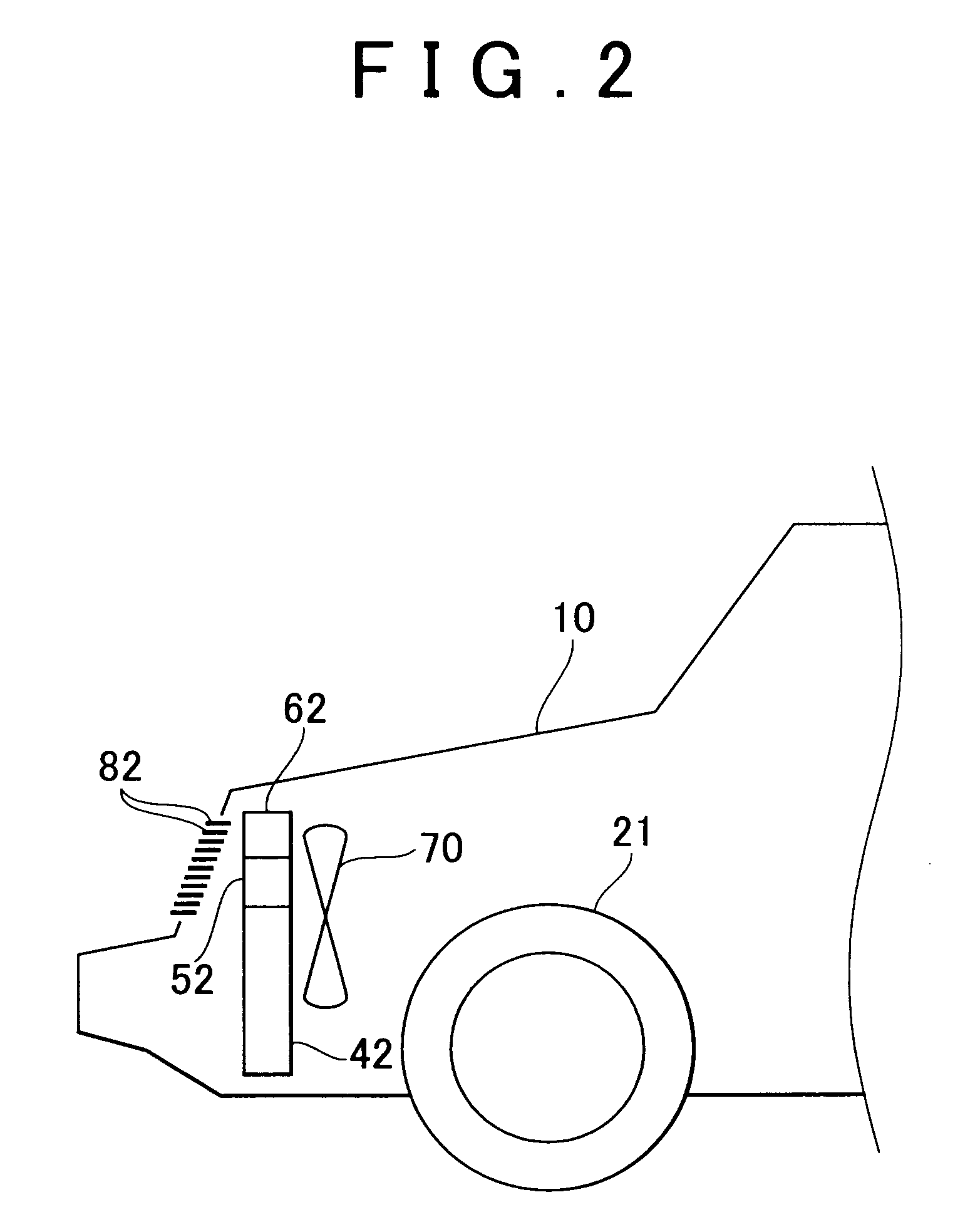
[0025]FIG. 1 is a diagram showing an outline of a configuration of a fuel cell vehicle 10 including a cooling system 30 according to an embodiment of the invention. FIG. 2 is an explanatory diagram showing an example of arrangement of heat exchangers of the cooling system 30 according to the embodiment of the invention. The fuel cell vehicle 10 in the embodiment includes a driving system 11 and a cooling system 30. The driving system 11 includes a fuel cell device 12 including a polymer electrolyte fuel cell stack, as an electric power source; an inverter 14 which converts direct electric current from the fuel cell device 12 to three phase alternating current; a motor for running 16 which drives a driving wheel 21 using the three phase alternating current from the inverter 14; a DC / DC converter 18 which is connected to two lines connecting the motor for running 16 to the fuel cell device 12; and a battery 20 whic...


PUM

PropertyMeasurementUnit
operating temperatureaaaaaaaaaa

Abstract

A FC radiator in a FC cooling system, an EV radiator in a driving device cooling system, and a condenser in an air conditioning cooling system are arranged in one plane substantially perpendicular to a direction in which a fuel cell vehicle moves forward at a front portion of the fuel cell. Also, heat exchangers are arranged in order of the condenser, the EV radiator, and the FC radiator, that is, in order of an operating temperature from an upper position to a lower position. An angle of plural fins fitted to a front grille is changed according to a load of a fuel cell and a vehicle speed, each of the plural fins being formed to have an elongate rectangular plate shape extending in a horizontal direction.

Description

INCORPORATION BY REFERENCE[0001]The disclosure of Japanese Patent Application No. 2004-150358 filed on May 20, 2004, including the specification, drawings and abstract is incorporated herein by reference in its entirety.BACKGROUND OF THE INVENTION[0002]1. Field of the Invention[0003]The invention relates to a cooling system and a hybrid vehicle including the cooling system. More specifically, the invention relates to a cooling system installed in a moving body, and a hybrid vehicle as the moving body including the cooling system.[0004]2. Description of the Related Art[0005]An example of such a cooling system is disclosed in Japanese Patent Application Publication No. JP (A) 2001-174168. As shown in FIG. 1 of the Japanese Patent Application Publication No. JP (A) 2001-174168, the cooling system includes two heat exchangers, that are, a heat exchanger for an electronic component (hereinafter, referred to as “electronic component heat exchanger”) through which coolant for the electroni...

Claims


Application Information

Patent Timeline
Patent Type & Authority Patents(United States)
IPC IPC(8): B60H1/32B60K1/04B60H1/00B60H1/22B60K6/22B60K6/40B60K8/00B60K11/04B60L11/18F17C9/04F25B39/04F28D1/04H01M8/02H01M16/00
CPCB60H1/004B60H1/00764B60H1/00828F28D1/0443H01M8/04067Y02E60/50H01M16/003H01M2250/20Y02T90/32Y02T90/40
Inventor HOSHI, JUNMAEDA, KAZUHIROICHIKAWA, SUSUMU
Owner TOYOTA JIDOSHA KK
Learn More