
Self-contained inertial navigation system for interactive control using movable controllers

a technology of inertial navigation and movable controller, which is applied in the field of self-contained inertial navigation systems (ins) for interactive control using movable controllers, can solve the problems of burdensome external signal source use, device dependent on light sources, and insufficient use of single tri-axial accelerometer to calculate all six degrees of freedom, etc., and achieve accurate determination of starting position and orientation

Active Publication Date: 2009-12-22
AILIVE
View PDF30 Cites 107 Cited by
  • Summary
  • Abstract
  • Description
  • Claims
  • Application Information

AI Technical Summary

Benefits of technology

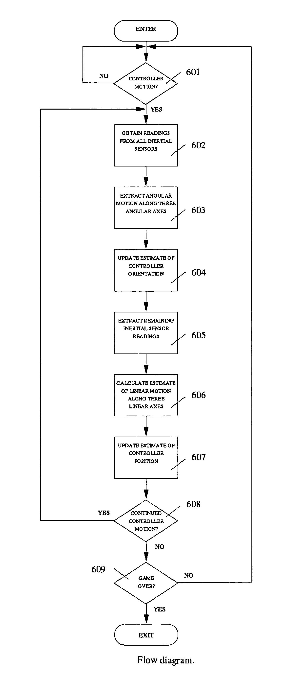
[0010]In one embodiment, the present invention involves incorporating a plurality of self-contained inertial sensors into a movable controller, and correlating the motion sensed by each sensor, so that both the three dimensional linear path and the angular orientation of the moving controller may be accurately tracked. For best results, the plurality of self-contained inertial sensors must be capable of tracking along six axes: three for linear acceleration along the three linear axes, and three axes for determining angular motion. Thus, the combination of one tri-axial accelerometer and one tri-axial gyroscope in the movable controller will function very effectively. However, those skilled in the art will be aware that various other combinations of sensors will also function effectively. For example, six accelerometers can be arranged in a known layout to provide an effective INS system for interactive control using a movable controller.
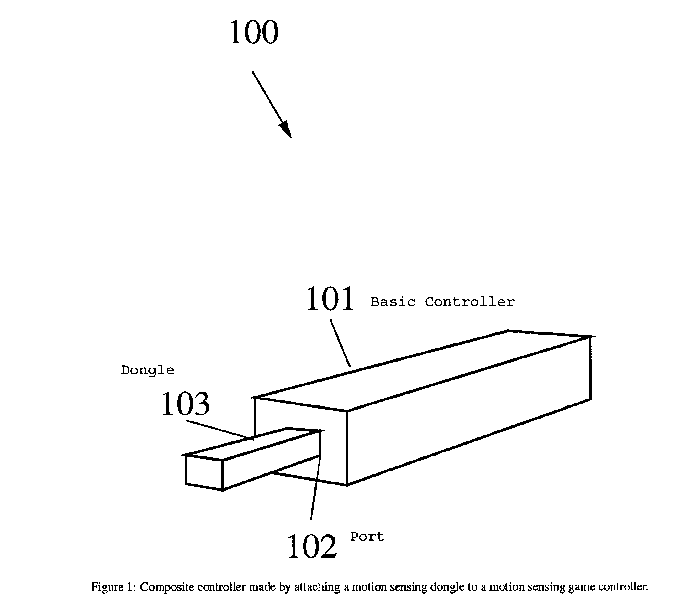
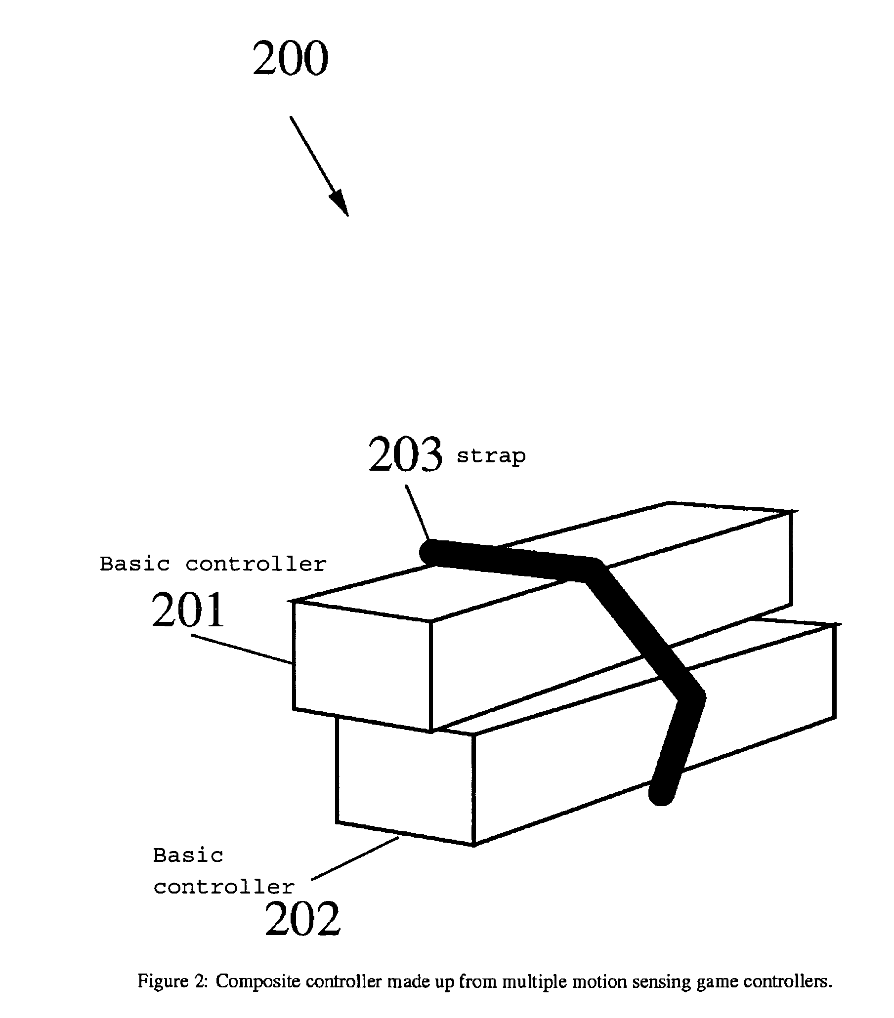
[0012]If the composite controller still does not provide sensing along all six axes, it may still be more useful than the basic controller. In particular, the constraints under which the user may hold and move the controller might be able to be relaxed without damaging the ability to track the composite controller's linear and angular motion.
[0016]In accordance with another aspect of the invention, a computer game system is provided in which aspects of the game are controlled by the above defined movable controllers having apparatus for determining their linear and angular motion. For example, a game might interpret the motion of the controller to drive the animation of a sword on the game display such that the sword on the display moves in an ostensibly similar manner to the motion of the controller. Since a self-contained INS system can only track motion relative to the position and orientation of the controller when tracking began, the game may assume the controller was held in some initial starting position and orientation, in which case, the motion applied to the on screen object being controlled will only be correct with respect to this assumption about the initial starting position and orientation. Additional sensors, possibly not self-contained, and techniques could be used to more accurately determine the starting position and orientation.

Problems solved by technology

But the use of light sensors means that the device depends on the light sources and is not, therefore, self-contained.
The use of external signal sources is burdensome because the user must set up and configure those external sources.
However, a single tri-axial accelerometer is insufficient to calculate all six degrees of freedom required to infer the linear and angular motion of a movable controller.
In fact, it is impossible to even determine whether the controller is being translated or rotated, since a fixed rotation and a linear acceleration could generate the same set of readings on a single tri-axial accelerometer.
However, by making assumptions on how the controller is held and along which axis it will be moved, it is sometimes possible to track the relative linear and angular motion.
But there is a wide class of games and other applications where it is undesirable to constrain how the user may move or hold the movable controller.
State of the art movable controllers are therefore unnecessarily limiting.

Method used


Image

  • Self-contained inertial navigation system for interactive control using movable controllers
  • Self-contained inertial navigation system for interactive control using movable controllers
  • Self-contained inertial navigation system for interactive control using movable controllers

Examples


Embodiment Construction

Definitions

[0024]In the description of the invention herein, above and hereinafter, the following definitions are offered to clarify the terminology used:

[0025]Self-contained inertial sensor: a device that requires no external signal sources to be placed in the environment for measuring acceleration of a moving body along from one to three axes of the six possible linear and angular axes. Unless stated otherwise, the word sensor is understood to refer to a self-contained inertial sensor. For illustrative purposes, in this document, we describe instantiations using accelerometers and gyroscopes. However, those skilled in the art would immediately recognize that other devices could be used as self-contained inertial sensors. For example, a camera that compares images over time (such as the camera used in an optical mouse) could be used as a self-contained inertial sensor. But an infrared camera that is designed to work by tracking infrared sources or markers that have been deliberatel...


PUM


Abstract

A movable game controller for controlling aspects of a computer controlled game display with apparatus for determining the linear and angular motion of that movable controller. The apparatus includes a plurality of self-contained inertial sensors for sensing the tri-axial linear and tri-axial angular motion of the moving controller. Each sensor is mounted at a fixed linear position and orientation with respect to the others. The linear and angular motion of the controller is computed from the correlated motion sensor readings of each of the plurality of self-contained inertial sensors.

Description

BACKGROUND OF THE INVENTION[0001]1. Field of Invention[0002]The present invention relates to self-contained inertial navigation systems (INS) for interactive control using movable controllers in applications like computer display games.[0003]2. Related Art[0004]The Nintendo Wii Remote™ wireless controller is an example of the most recent state of the art advances in user interactive controllers for computer display game systems. It is a movable wireless remote controller, which is hand-held by the interactive user, that transmits input data to the computer controlled game display system via conventional short range wireless RF transmissions e.g., a Bluetoothsystem, and receives data via infra-red light sensors. This game controller is described in detail in Published U.S. Application US2007 / 0060384, (Mar. 15, 2007).[0005]With movable controllers for game systems like the Nintendo Wii, it is desirable to use a self-contained INS system to sense and track the relative linear and ang...

Claims


Application Information

Patent Timeline
IPC IPC(8): G06F3/00
CPCA63F13/02A63F13/06G06N99/005G06F3/0346A63F2300/105A63F2300/1043G06N20/00A63F2300/1006A63F2300/1087A63F13/98A63F13/833A63F13/92A63F2300/8029A63F13/213A63F2300/204A63F13/24A63F2300/1031A63F13/235A63F13/211
Inventor YEN, WEIWRIGHT, IANTU, XIAOYUANREYNOLDS, STUARTPOWERS, III, WILLIAM ROBERTMUSICK, CHARLESFUNGE, JOHNDOBSON, DANIELBERERTON, CURT
Owner AILIVE
Learn More