
Method and apparatus for precisely aligning integrated circuit chips

a technology of integrated circuit chips and wafers, applied in the direction of individual semiconductor device testing, semiconductor/solid-state device testing/measurement, instruments, etc., can solve the problems of wire bonding typically limited to a few rows, bottlenecks that are expected to worsen, and advances in semiconductor technology that cannot match the corresponding advances in inter-chip communication technology. to achieve the effect of facilitating precise inter-chip alignmen

Active Publication Date: 2009-11-17
ORACLE INT CORP
View PDF39 Cites 13 Cited by
  • Summary
  • Abstract
  • Description
  • Claims
  • Application Information

AI Technical Summary

Benefits of technology

This solution enables precise alignment of integrated circuit chips, overcoming the limitations of traditional die bonding methods by allowing for remateability and precise control of chip separation, thereby enhancing inter-chip communication bandwidth and reducing production costs.

Problems solved by technology

However, these semiconductor chips still need to communicate with other chips, and unfortunately, these advances in semiconductor technology have not been matched by corresponding advances in inter-chip communication technology.
This problem is creating a bottleneck that is expected to worsen as semiconductor integration densities continue to increase.
Furthermore, wire bonds are typically limited to a few rows.
Hence, wire bonds generally cannot be used to provide a large fully populated two-dimensional array of terminals.

Method used


Image

  • Method and apparatus for precisely aligning integrated circuit chips
  • Method and apparatus for precisely aligning integrated circuit chips
  • Method and apparatus for precisely aligning integrated circuit chips

Examples


Embodiment Construction

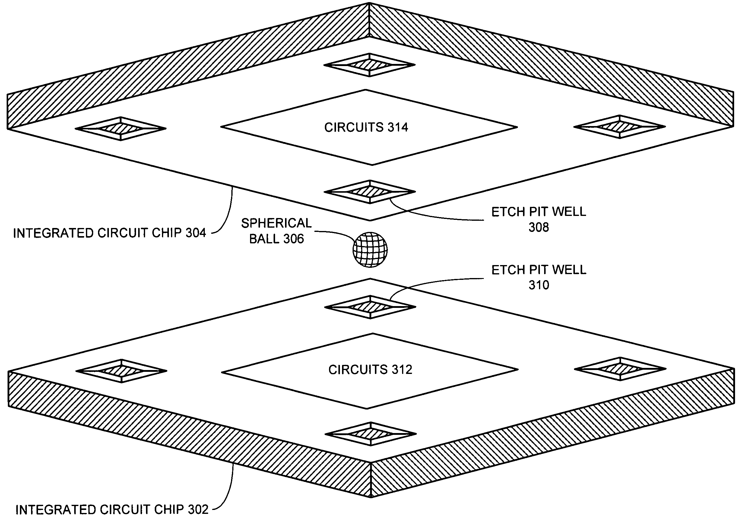
[0033]The following description is presented to enable any person skilled in the art to make and use the invention, and is provided in the context of a particular application and its requirements. Various modifications to the disclosed embodiments will be readily apparent to those skilled in the art, and the general principles defined herein may be applied to other embodiments and applications without departing from the spirit and scope of the present invention. Thus, the present invention is not limited to the embodiments shown, but is to be accorded the widest scope consistent with the principles and features disclosed herein.

Alignment of Integrated Circuit Chips

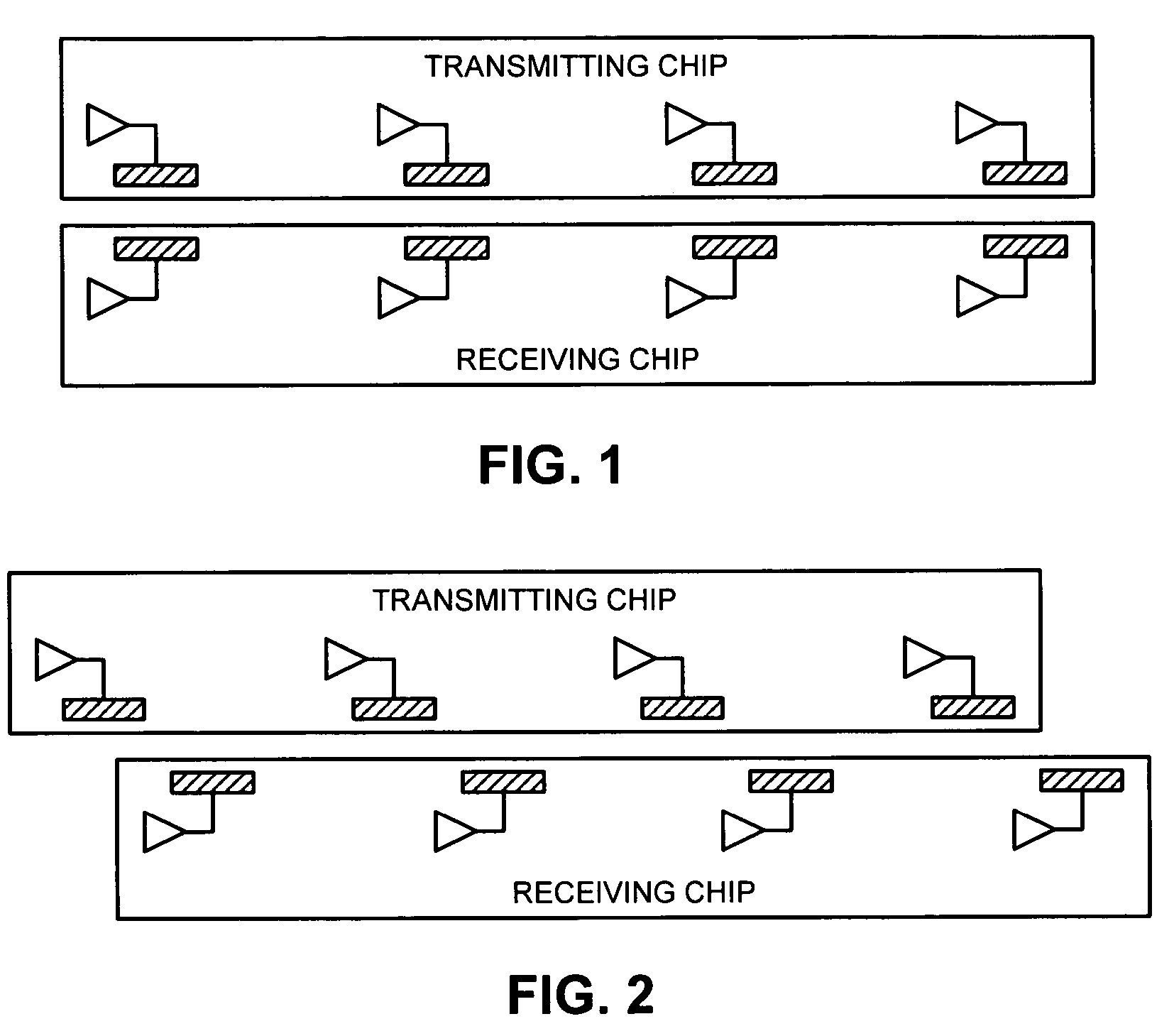
[0034]The present invention relates to a structure and a technique for aligning and interconnecting two integrated circuit chips with improved accuracy. Note that such integrated circuit chips that use Proximity Communication to communicate with each other require precision alignment not only laterally but also in axially ...


PUM


Abstract

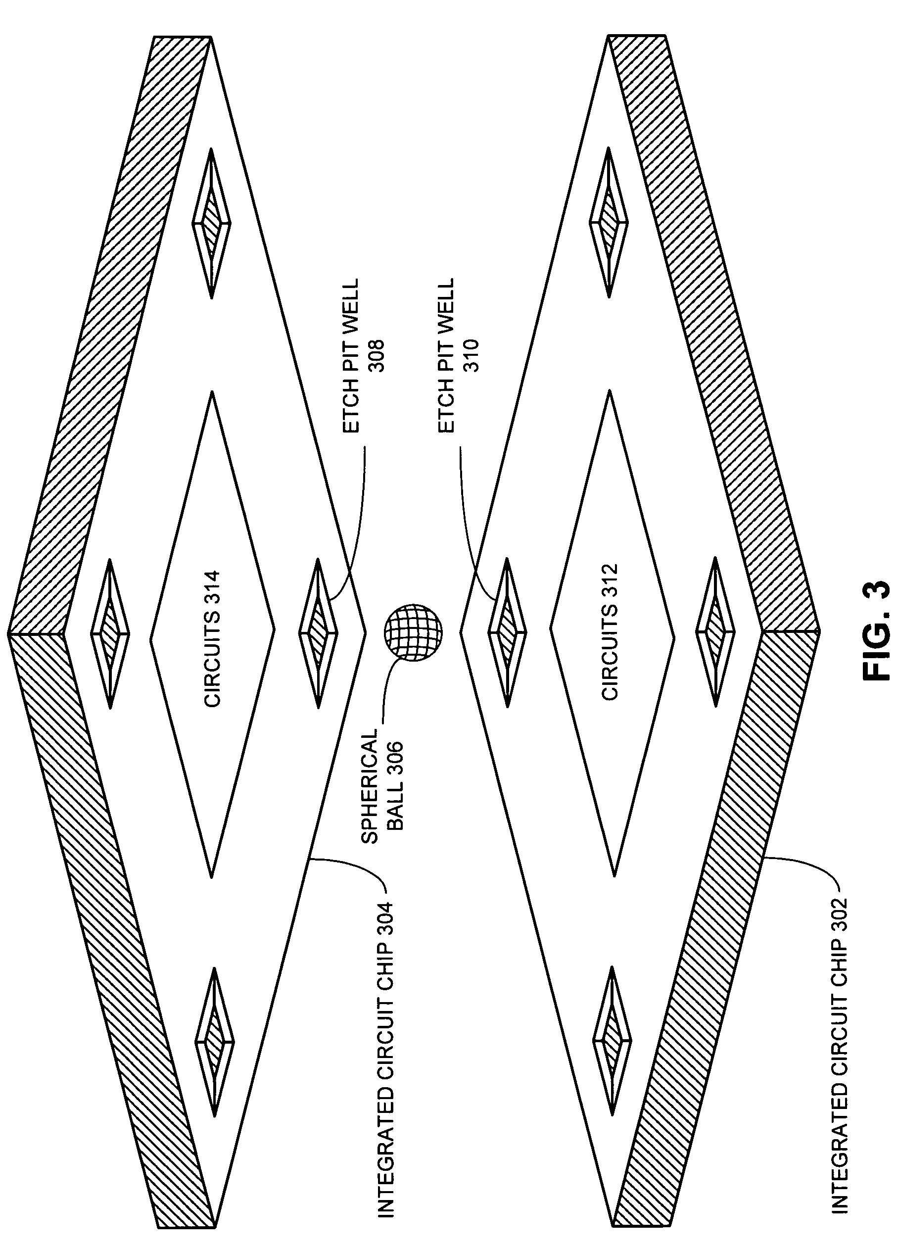
A system that facilitates precise inter-chip alignment. The system includes a first integrated circuit chip, whose surface has etch pit wells. The system also includes a second integrated circuit chip, whose surface has corresponding etch pit wells that mate with the etch pit wells of the first integrated circuit chip. Spherical balls are placed in the etch pit wells of the first integrated circuit chip such that when the corresponding etch pit wells of the second integrated circuit chip are substantially aligned with the spherical balls, the spherical balls mate with the etch well pits of the second integrated circuit chip, thereby precisely aligning the first integrated circuit chip with the second integrated circuit chip.

Description

GOVERNMENT LICENSE RIGHTS[0001]This invention was made with United States Government support under Contract No. NBCH020055 awarded by the Defense Advanced Research Projects Administration. The United States Government has certain rights in the invention.BACKGROUND[0002]1. Field of the Invention[0003]The present invention relates to a technique for precisely aligning integrated circuit chips or wafers.[0004]2. Related Art[0005]Advances in semiconductor technology presently make it possible to integrate large-scale systems, including tens of millions of transistors, onto a single semiconductor chip. Integrating such large-scale systems onto a single semiconductor chip increases the speed at which such systems can operate, because signals between system components do not have to cross chip boundaries, and are not subject to lengthy chip-to-chip propagation delays. Moreover, integrating large-scale systems onto a single semiconductor chip significantly reduces production costs, because ...

Claims


Application Information

Patent Timeline
Patent Type & Authority Patents(United States)
IPC IPC(8): H01L23/48H01L21/00H01L31/00H01L29/40H01L23/544H01L23/52H01L21/66H01L23/02
CPCH01L23/48H01L24/10H01L24/13H01L24/72H01L24/73H01L24/81H01L24/83H01L24/90H01L25/0657H01L2224/81141H01L2224/81138H01L2924/10253H01L2225/06593H01L2225/06531H01L2924/0665H01L2924/01033H01L2224/13099H01L2224/81136H01L2224/81801H01L2224/83136H01L2224/83194H01L2224/838H01L2224/83851H01L2225/06527H01L2924/01027H01L2924/01075H01L2924/01079H01L2924/10157H01L2924/14H01L2924/3011H01L2924/3025H01L2224/2919H01L2924/00H01L2924/00014H01L2224/13
Inventor KRISHNAMOORTHY, ASHOK V.CUNNINGHAM, JOHN E.FOLLMER, EDWARD LEE
Owner ORACLE INT CORP
Learn More