Optical measuring device using optical triangulation

a technology of optical triangulation and measuring device, which is applied in the direction of optical radiation measurement, instruments, photometry, etc., can solve the problems of insufficient measurement precision, too expensive, and complicated means (in particular optical means) employed, and achieve greater reliability, greater measurement precision, and greater simplicity in the arrangement of the device

Inactive Publication Date: 2009-11-10
SAGEM DEFENSE SECURITE SA
View PDF12 Cites 8 Cited by
  • Summary
  • Abstract
  • Description
  • Claims
  • Application Information

AI Technical Summary

Benefits of technology

[0009]The object of the invention is therefore to propose an improved technical solution based on optical triangulation, which meets the various requirements of the practice more satisfactorily, especially as regards achi

Problems solved by technology

However, these known devices have various drawbacks from the structural standpoint (for example moving optical parts, such as oscillating mirrors) and/or from the optical standpoint (for example microstructured image formatio

Method used


Image

  • Optical measuring device using optical triangulation
  • Optical measuring device using optical triangulation
  • Optical measuring device using optical triangulation

Examples


Embodiment Construction

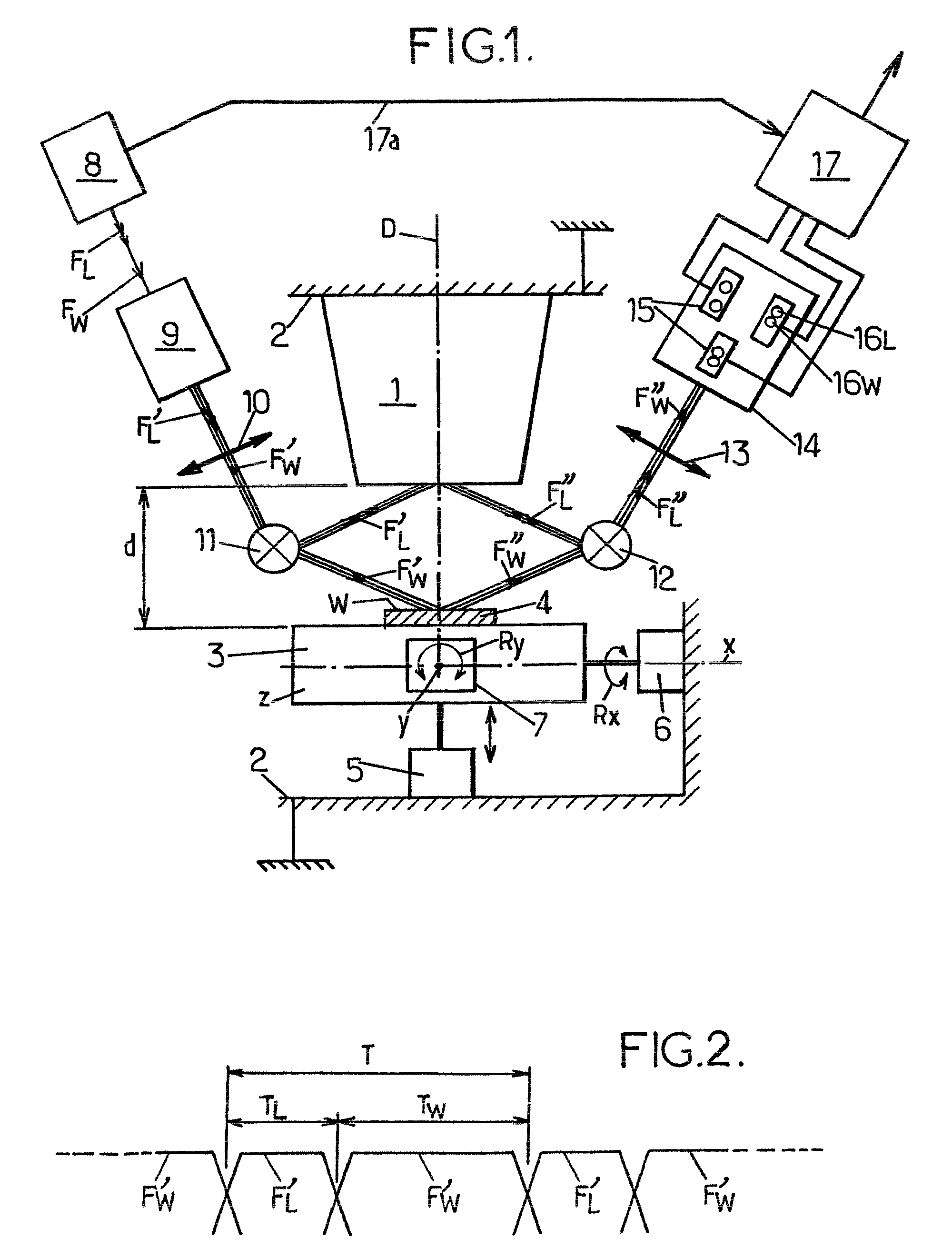
[0046]Shown highly schematically in FIG. 1 is an optical measuring device using optical triangulation or profilometry for measuring, with respect to a plane reference surface L and along a direction D substantially perpendicular to the latter, the distance d and the inclination Rx and Ry in two directions x and y of a surface W to be checked, which locally can be likened to a plane. In other words, the measuring device is capable of measuring the attitude of the surface W with respect to the reference surface L, the two directions x and y defining the surface W to be checked and the direction D corresponding approximately to the direction z perpendicular to the directions x and y.

[0047]In FIG. 1, the device is schematically shown within the context of the application more especially envisioned for the practical implementation of the invention, namely a microphotolithography apparatus possessing an objective 1, the optical axis of which is said direction D, which objective is fastene...


PUM


Abstract

An optical triangulation measuring device includes an emmiter that emits two alternating light beams with different wavelengths along the same path; a beam splitter; an optical separator that directs the alternating split beams towards the surfaces from which they are reflected; an optical combiner that collects the beams and directs them along a path; optronic sensors that receive two light images and to deliver a signal indicating the position of the energy barycenter a time synchronizer for the two alternating beams and the two images on the optronic sensors; and a processor for processing the signals from the optronic sensors in order to supply information relating to the position and inclination of the surface.

Description

FIELD OF THE INVENTION[0001]The present invention relates in general to the field of optical distance and / or inclination measurement by optical triangulation (or optical profilometry) and relates more particularly to improvements made to optical measuring devices using optical triangulation for measuring, relative to a plane reference surface and in a direction substantially perpendicular to said reference surface, the distance and the inclination in two directions of a surface to be measured, which locally can be likened to a plan. The distance and the inclination may be constants over time or else they may change.BACKGROUND OF THE INVENTION[0002]Measuring devices of this type find particularly advantageous application in the field of microphotolithography (fabrication of microcircuits on a substrate of semiconductor material, for example typically silicon, by exposure, by means of light radiation, for example ultraviolet radiation, of a resist deposited on the surface of this subs...

Claims


Application Information

Patent Timeline
IPC IPC(8): G01B11/14G01J1/00
CPCG03F9/7026G03F9/7034G03F9/7088G03F9/7065G03F9/7049
Inventor MICHELIN, JEAN-LUC
Owner SAGEM DEFENSE SECURITE SA
Why Eureka
Try Eureka