
Collapsible structure with integrated sleeve junction

a technology of collapsible structures and junctions, which is applied in the field of collapsible, portable structures, can solve the problems of large labor costs, large volume, and difficult movement of greenhouses, and achieve the effect of sufficient flexibility and sufficient resiliency

Active Publication Date: 2009-11-10
WORLDWIDE CREATIONS
View PDF33 Cites 26 Cited by
  • Summary
  • Abstract
  • Description
  • Claims
  • Application Information

AI Technical Summary

Benefits of technology

[0009]The present invention is a portable, collapsible structure having a frame element disposed within a sleeve defining a perimeter of at least one wall. A roof is connected to the at least one wall at a seam, wherein a portion of the sleeve is connected to the seam, and wherein the roof and the at least one wall define an interior of the structure. The portion of the sleeve connected to the seam is disposed within the interior of the structure. The roof and at least one wall may further comprise a flexible material such as nylon, canvas, or polyethylene. Further, the frame element may additionally comprise a continuous band of resilient material. Such a band of resilient material may have sufficient flexibility to be coiled without breaking and sufficient resiliency to substantially return to and maintain its original shape. Steel may be such a suitable resilient material.

Problems solved by technology

Unfortunately, these sorts of greenhouses are small and often unsightly in home use applications.
Such devices, even when claiming to be portable, are generally bulky, labor-intensive, and difficult to move.
At the other end of the spectrum are greenhouse devices that, while portable, are so flimsy as to require frequent repair and replacement.
Such structures have difficulty surviving even moderate weather conditions and are easily damaged in one or more of the set-up, take-down, or storage processes.
Some of these shortfalls include material decay from prolonged exposure to ultraviolet radiation, as well as having edges and seams that may invite the collection of debris in the course of prolonged use.

Method used


Image

  • Collapsible structure with integrated sleeve junction
  • Collapsible structure with integrated sleeve junction
  • Collapsible structure with integrated sleeve junction

Examples


Embodiment Construction

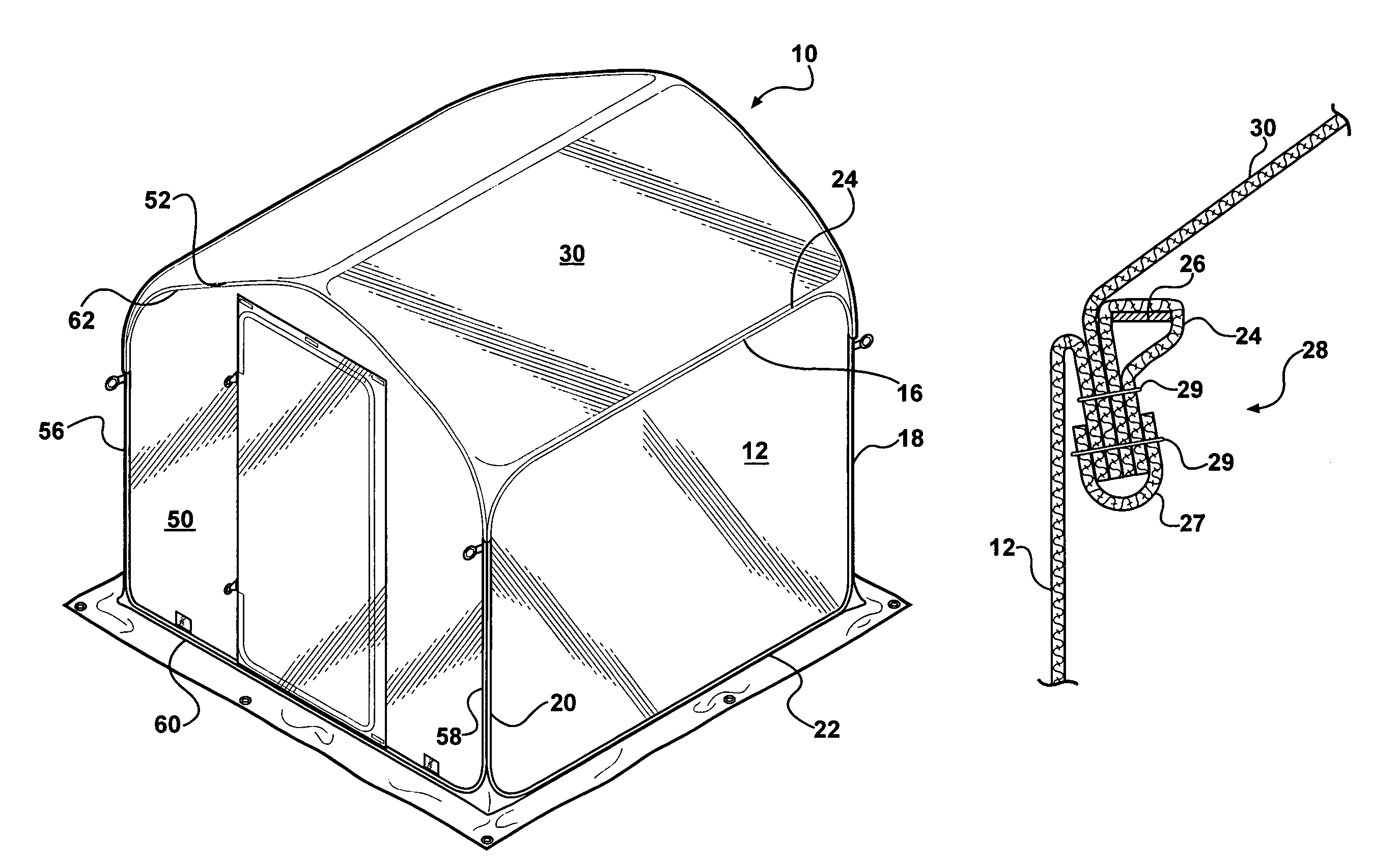
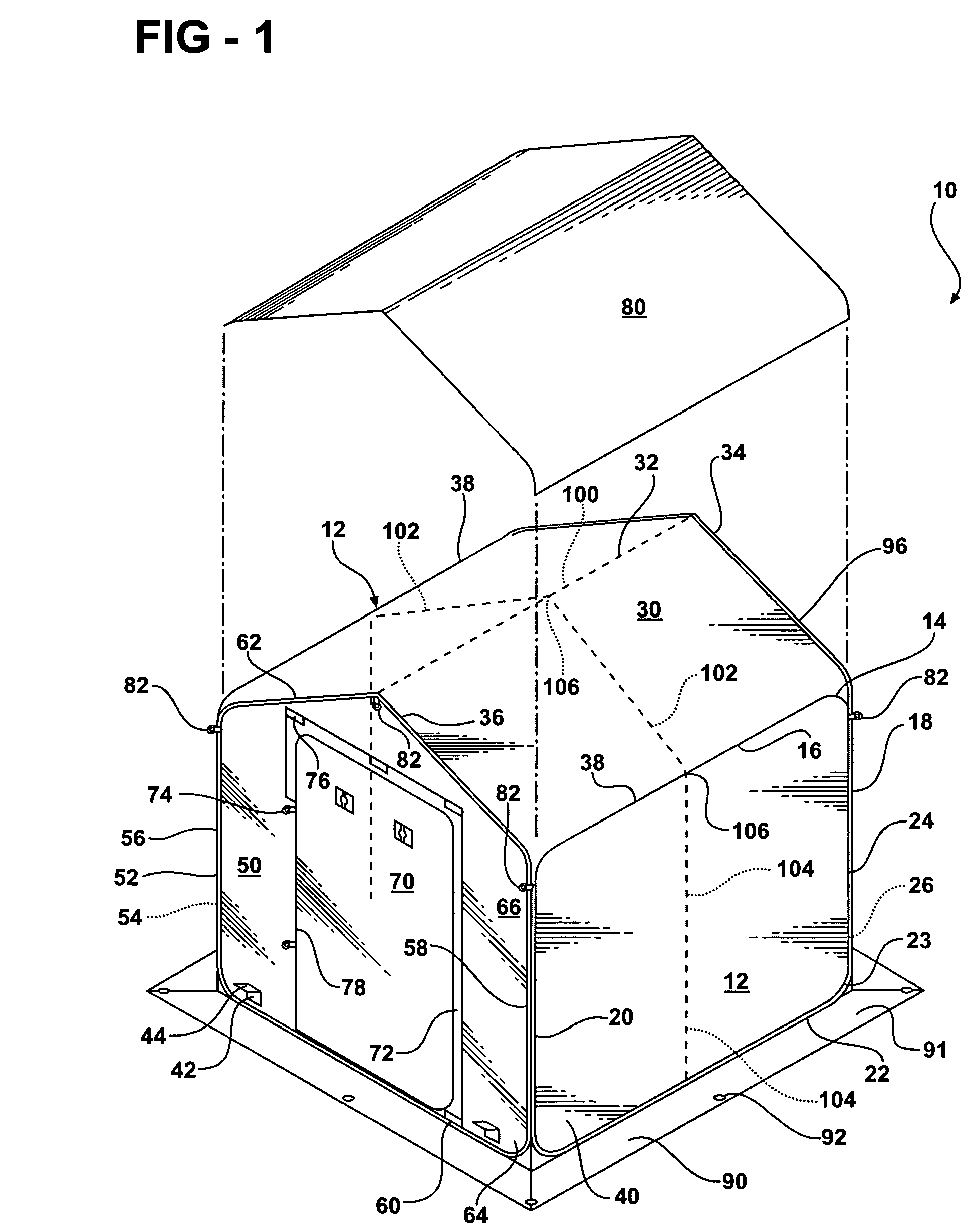
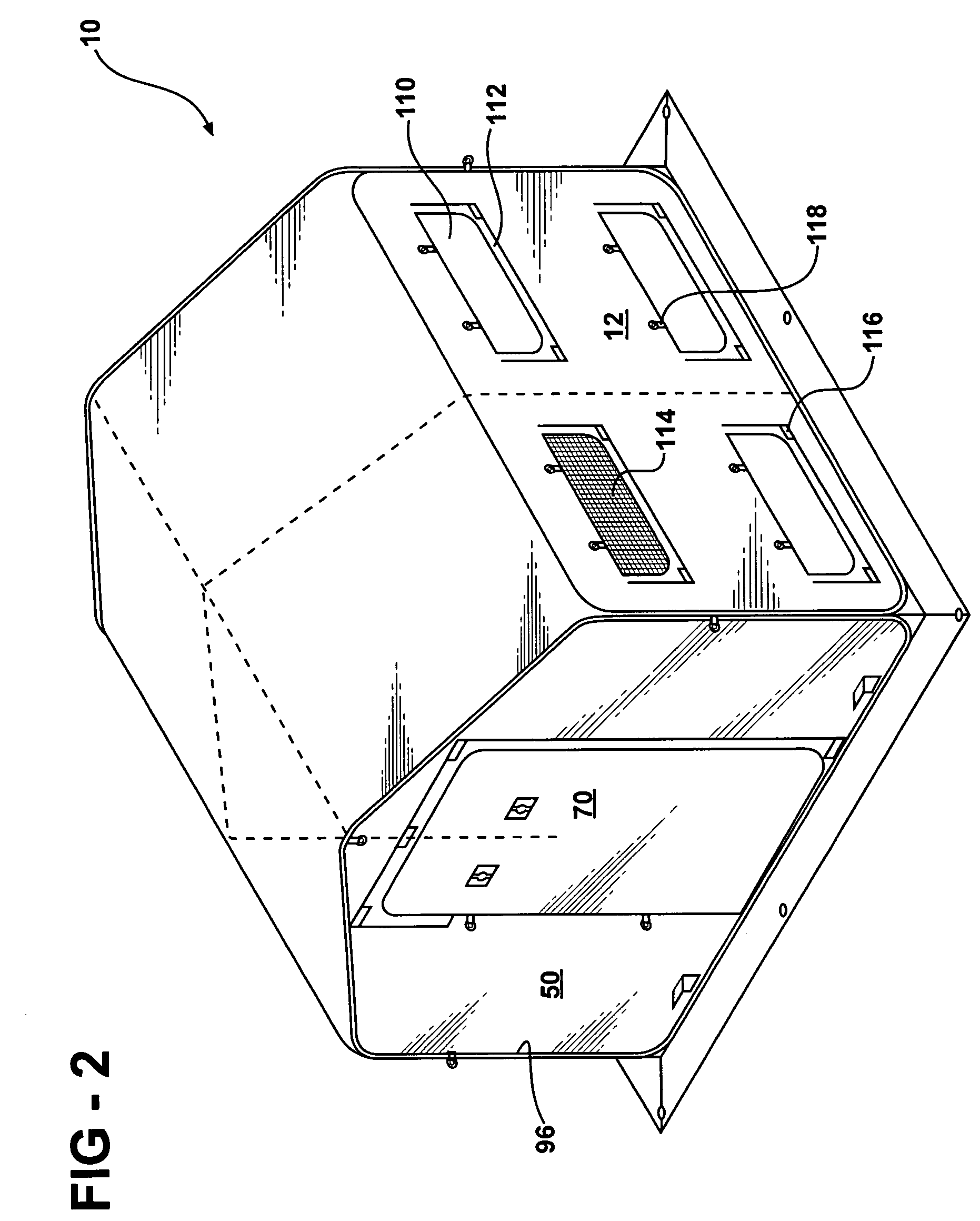
[0020]FIG. 1 illustrates a collapsible structure or greenhouse 10. The greenhouse 10 is formed from sidewalls 12, end walls 50, and roof 30. Each of the walls 12, 50, and roof 30 consist of a covering material 40 connected to and extending about rigid or semi-rigid frame members 26.

[0021]The side walls 12 of the greenhouse 10 are substantially rectangular in shape, although the present invention anticipates that various geometries may be utilized. The side walls 12 each have a top edge 16, back edge 18, front edge 20, and bottom edge 22. These edges, 16, 18, 20, 22, meet at radiused corners 23. The edges 16, 18, 20, 22 and corners 23 constitute a perimeter 14 of each side wall 12. Coincident with the perimeter 14 of side walls 12 is a sleeve 24 containing a resilient frame member 26. The sleeve 24 may be formed as a hem in covering material 40 of the side walls 12 or may be made of other suitable material and attached to the perimeter 14 of the covering material 40 of the side walls...


PUM


Abstract

A portable, collapsible structure having a frame element disposed within a sleeve, defining a perimeter of at least one wall is disclosed. A roof is connected to the at least one wall at a seam, wherein a portion of the sleeve is connected to the seam, and wherein the roof and the at least one wall define an interior of the structure. The portion of the sleeve connected to the seam is disposed within the interior of the structure. The roof and at least one wall may further comprise a flexible material such as nylon, canvas, or polyethylene. Further, the frame element may additionally comprise a continuous band of resilient material. Such a band of resilient material may have sufficient flexibility to be coiled without breaking and sufficient resiliency to substantially return to and maintain its original shape. Steel may be such a suitable resilient material.

Description

[0001]This is a continuation-in-part application of U.S. patent application Ser. No. 10 / 889,675, filed Jul. 13, 2004, which claims the benefit of U.S. Provisional Application No. 60 / 496,108, filed Aug. 19, 2003.FIELD OF THE INVENTION[0002]The present invention relates to a collapsible, portable structure, and more particularly, to a collapsible, portable structure having an integrated sleeve junction that can be utilized as a greenhouse, hunting blind, or other temporary structure wherein the structure is easily folded into a compact package for ease of transportation and storage.BACKGROUND OF THE INVENTION[0003]Gardening, both for food production and recreation, is becoming increasingly popular. Greater numbers of gardeners are utilizing small greenhouses to protect plants from inclement weather while still ensuring continued exposure of the growing plants to sunlight. The use of greenhouses for home gardening is well known. Such greenhouses come in a variety of shapes and sizes. G...

Claims


Application Information

Patent Timeline
Patent Type & Authority Patents(United States)
IPC IPC(8): E04H15/40
CPCA01G9/16Y02A40/25
Inventor WEHNER, SCOTT D.
Owner WORLDWIDE CREATIONS
Learn More