
Angular position adjusting mechanism

a technology of adjusting mechanism and angular position, which is applied in the direction of gearing, hoisting equipment, chairs, etc., can solve the problems of large load liable to act on the gear, disadvantageous background art in ensuring meshing strength, etc., and achieves the effect of increasing the strength of teeth, and reducing the risk of gear damag

Active Publication Date: 2009-11-03
AISIN SEIKI KK
View PDF31 Cites 8 Cited by
  • Summary
  • Abstract
  • Description
  • Claims
  • Application Information

AI Technical Summary

Benefits of technology

[0006]Accordingly, a technical problem to be solved by the invention is to obtain an angular position adjusting mechanism using an internal gear and an external gear, which have tooth profiles that provides higher meshing strength.
[0024]According to the configuration of (1), the following advantages are obtained. That is, because the tooth profiles are formed according to the trochoid curve, a large contact ratio is obtained in a meshing range in which the internal gear and the external gear mesh with each other. Moreover, the loop shapes are used, so that the inclination of the tooth flat at the meshing point, at which the gears abut against each other, can be set to be smaller than that of a surface perpendicular to the direction of rotation of the external gear. Thus, the strength of teeth can be increased.
[0025]According to the configuration of (2), (3), (5), (7), (8), and (10), a press working die for forming the tooth profiles of the internal gear and the external gear, to which the trochoid curves are applied, can be made with high precision by using a numerically controlled machine tool. Consequently, the tooth profiles of the gears can be formed with good accuracy. Also, the strength needed in designing the tooth profiles can easily be ensured.
[0026]According to the configuration of (4), (6), and (9), a gap is formed between each top land of the external gear and the associated bottom land of the internal gear and serves as a space, in which lubricating grease is accumulated. Thus, the securement of the durability of the gears is facilitated.
[0027]According to the configuration of (12), reduction in the number of components is enabled.
[0028]According to the configuration of (13) and (14), in a state in which the angular position is held, backlash is set to be small. Alternatively, when the angular position is adjusted, the adjustment thereof is performed so that backlash is set to be large. Thus, in a state in which the angular position is held, the meshing strength of the gears is set to be high. When the angular position is adjusted, the gears mesh and rotate with a light load to thereby enable an adjusting operation.

Problems solved by technology

However, the inclination D (see FIG. 7) of the tooth flank F to a surface E (see FIG. 7), which is perpendicular to the direction of rotation of the external gear, is large, so that a large load is liable to act upon the gear.
Therefore, the background art is disadvantageous in ensuring meshing strength.

Method used


Image

  • Angular position adjusting mechanism
  • Angular position adjusting mechanism
  • Angular position adjusting mechanism

Examples


Embodiment Construction

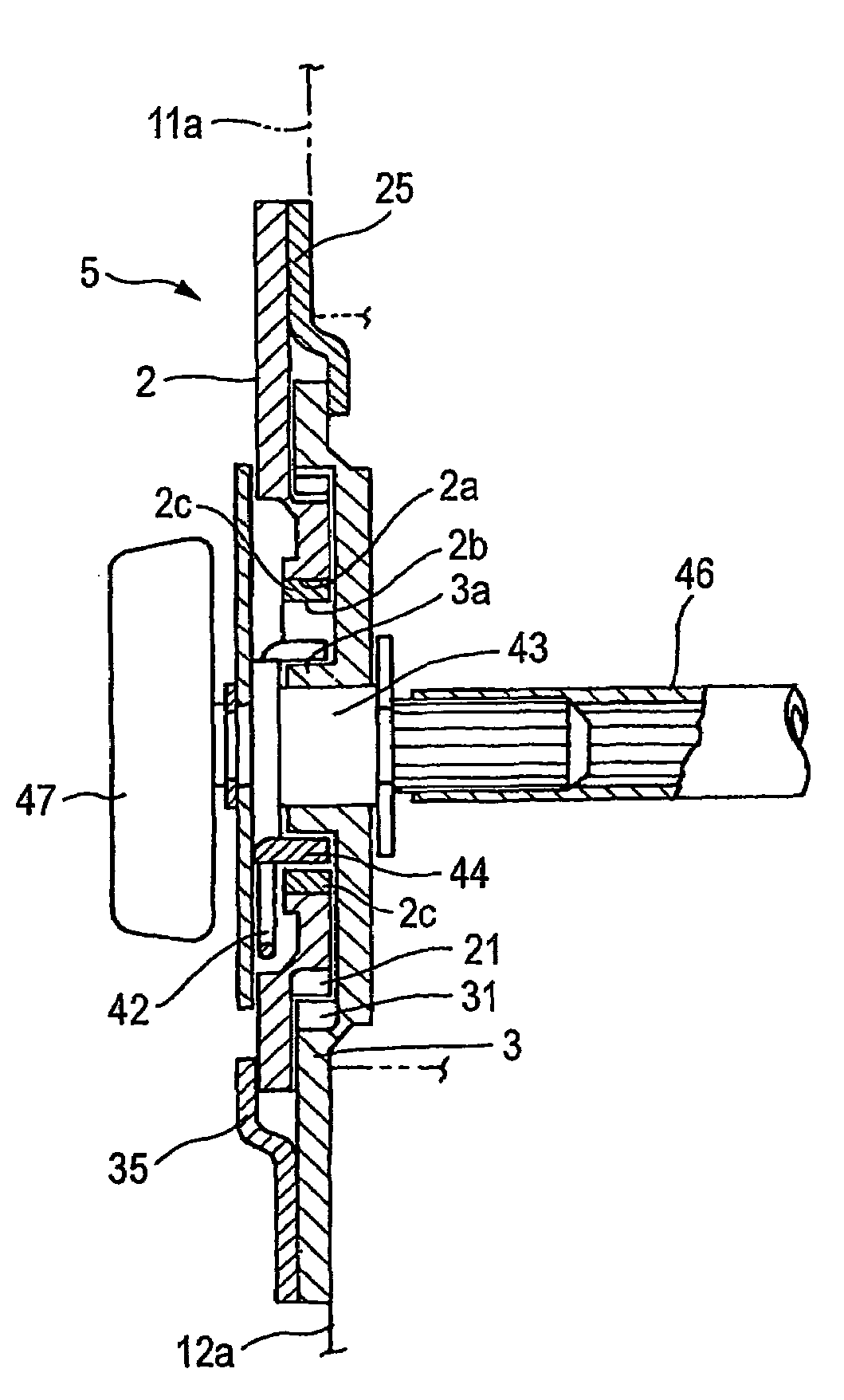
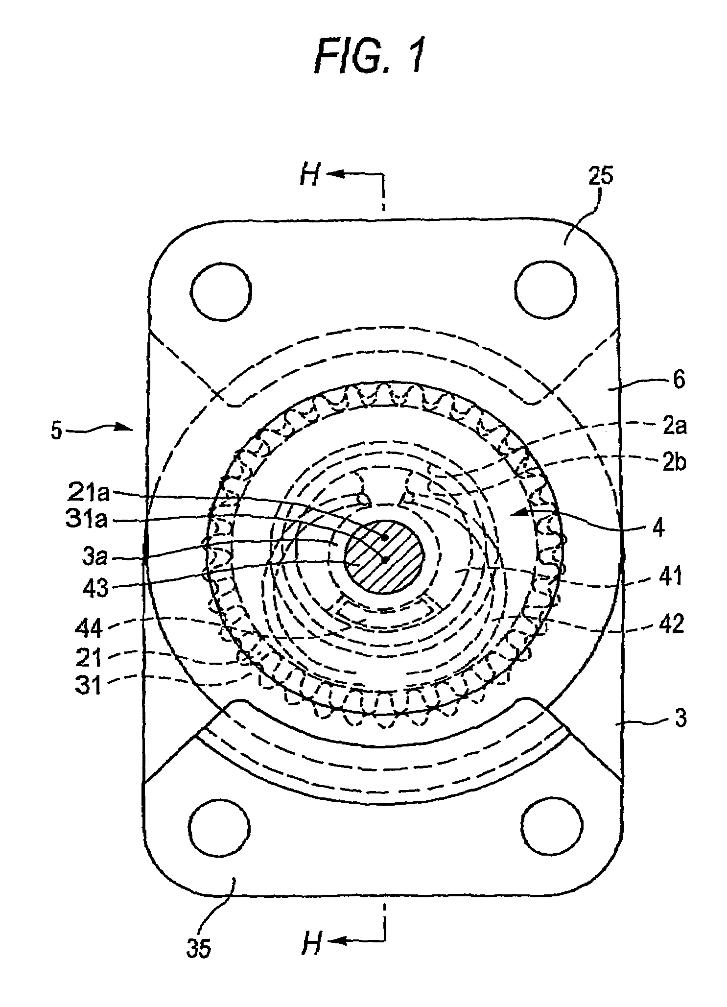
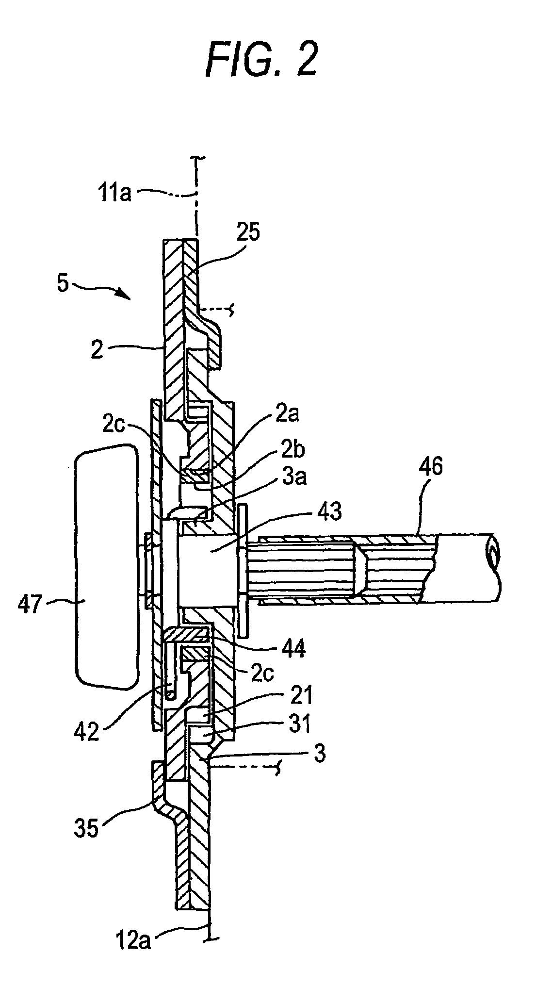
[0036]Hereinafter, an angular position adjusting mechanism 5, which is a first embodiment of the invention, is described with reference to FIGS. 1-4, and 6.

[0037]Referring to FIG. 6, the angular position adjusting mechanism 5 is applicable to, for example, a reclining apparatus 50 for adjusting a reclining angle of a seat back 11 of a vehicular seat 10, or to a vertical apparatus 60 for adjusting a height of a seat cushion 12 thereof. That is, the reclining apparatus 50 is configured so that the angular position adjusting mechanism 5 is mounted between a frame 11a of the seat back 11 and a frame 12a of the seat cushion 12, and that an angle of inclination of the seat back 11 can arbitrarily be adjusted by rotating an operating handle 47. When the operating handle 47 is not operated, predetermined strength is ensured so as to hold the position of the seat back 11. Thus, an occupant can be supported. Similarly, the vertical apparatus 60 is configured so that the angular position adjus...


PUM


Abstract

In an angular position adjusting apparatus, tooth profiles of an internal gear 31 and an external gear 21 are formed according to loop shapes 74a and 84a of predetermined trochoid curves 74 and 84.

Description

TECHNICAL FIELD[0001]The present invention relates to an angular position adjusting mechanism, which is employed as a mechanism for steplessly adjusting the angular position of a seat back of a vehicular seat or the height position of a seat cushion thereof and which needs strength in an angular position holding state thereof.BACKGROUND ART[0002]As shown in FIG. 7, such an angular position adjusting mechanism enabled to steplessly adjust the position is configured by forming an internal gear 231 in one of brackets and also forming an external gear 221 in the other bracket so that the internal gear 231 is meshed with the external gear 221, and that these gears are mutually rotatably combined with each other, to thereby enable the adjustment of the angular position and also enable the brackets to firmly hold the position.[0003]As shown in FIG. 3, the tooth profiles employed by these gears are formed according to a cycloid curve 274, which is the locus of a basic point 271 on the circu...

Claims


Application Information

Patent Timeline
Patent Type & Authority Patents(United States)
IPC IPC(8): F16H3/70B60N2/02B60N2/48F16H55/10F16H55/08F16H1/32B60N2/16B60N2/225B60N2/90
CPCB60N2/181B60N2/1842B60N2/2252B60N2/4435B60N2/1867Y10T74/19949B60N2/933A47C1/022A47C1/025B60N2/22B60N2/225
Inventor ITO, SADAO
Owner AISIN SEIKI KK
Learn More