
A fixing structure between a connector base and a circuit board

A technology of fixing structure and circuit board, applied in the direction of connection, circuit, fixed connection, etc., can solve the problems of human injury, insufficient terminal clamping force, high cost, and achieve the effect of reducing cost

Active Publication Date: 2021-11-23
DONGGUAN SIWEB CONNECTORS
View PDF5 Cites 0 Cited by
  • Summary
  • Abstract
  • Description
  • Claims
  • Application Information

AI Technical Summary

Problems solved by technology

[0003] 1. Welding method: The welding method is not only costly but also produces toxic gases (such as carbon monoxide, nitrogen oxides, etc.) during the welding process, which will cause harm to the human body
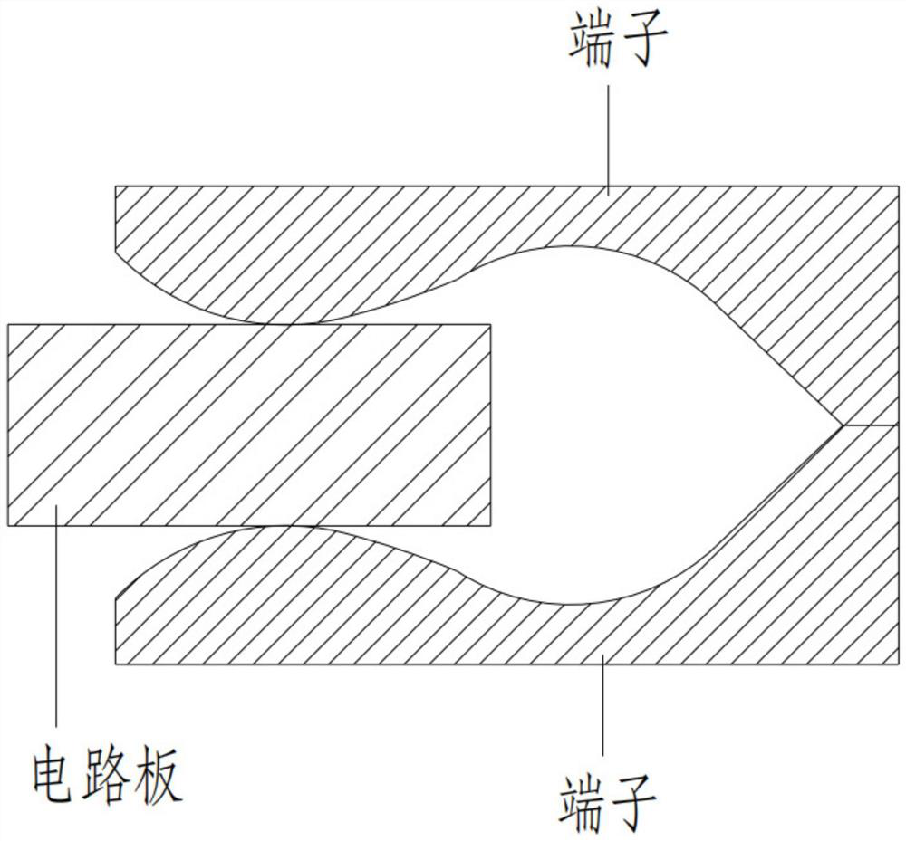
[0004] 2. Clamping method: please refer to figure 1 , the circuit board of the car controller is clamped by the terminals inside the board end, and the clamping force of the terminal is insufficient, resulting in an insecure connection between the board end and the circuit board of the car controller

Method used


Image

  • A fixing structure between a connector base and a circuit board
  • A fixing structure between a connector base and a circuit board
  • A fixing structure between a connector base and a circuit board

Examples


Embodiment Construction

[0025] In order to describe the technical solution of the present invention more clearly and completely, the present invention will be further described below in conjunction with the accompanying drawings.

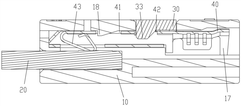
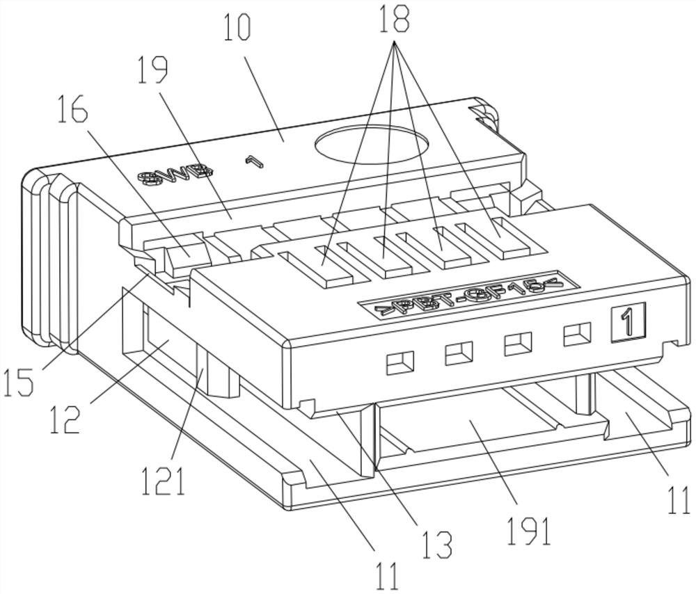
[0026] Please refer to Figure 2 to Figure 8 , the present invention proposes a fixing structure between the connector base and the circuit board, the fixing structure between the connector base and the circuit board includes a base 10, a circuit board 20 and an engaging member 30, and the circuit board 20 is provided with The first engaging plate 21, the base 10 is provided with a first positioning groove 11, and the first positioning groove 11 is also provided with a second engaging plate 12 and a first limiting plate 13 fixedly connected with the base 10 , there is a gap 14 between the second engaging plate 12 and the base body 10, the first engaging plate 21 is partially inserted into the first positioning groove 11 and engages with the second engaging plate 12, the O...


PUM


Abstract

The present invention proposes a fixing structure between a connector base and a circuit board, including a base body, a circuit board, and an engaging member. The circuit board is provided with a first engaging plate, and the base body is provided with a first positioning groove. There is also a second engaging plate and a first limiting plate fixedly connected to the base body, there is a gap between the second engaging plate and the base body, the first engaging plate is partially inserted into the first positioning groove and engaged with the second engaging plate, One end of the circuit board abuts against the first limiting plate, the other end of the circuit board abuts against the bottom wall of the first positioning groove, a second limiting plate is provided on the engaging part, the engaging part engages with the base body and the second limiting plate The positioning plate is accommodated in the gap, one end of the second limiting plate abuts against the second engaging plate, and the other end of the second limiting plate abuts against the side wall of the first positioning slot; The connection is to limit the deformation of the second engaging plate through the second limiting plate to increase the engaging strength between the circuit board and the base body, thereby maintaining a firm connection between the circuit board and the base body.

Description

technical field [0001] The invention relates to the field of automotive lamp connectors, in particular to a fixing structure between a connector base and a circuit board. Background technique [0002] The headlights and taillights of the car need to be connected to the car controller through a connector. The connector includes a wire end (male) and a board end (female seat). The specific connection structure is: the headlight, taillight and the wire end are connected, and the wire The end is inserted into the board end, and the board end is fixedly connected with the circuit board of the car controller; in order to prevent the board end from being separated from the circuit board of the car controller, the board end is fixedly connected with the circuit board of the car controller by welding or clamping , the disadvantages are as follows: [0003] 1. Welding method: The welding method is not only costly, but also produces toxic gases (such as carbon monoxide, nitrogen oxide...

Claims


Application Information

Patent Timeline
Patent Type & Authority Patents(China)
IPC IPC(8): H01R12/51
CPCH01R12/51
Inventor 董坤
Owner DONGGUAN SIWEB CONNECTORS
Learn More