An anchoring device for vibrating and shaping concrete used for building side walls of deep foundation pit modules
An anchoring device, deep foundation pit technology, applied in construction, sheet pile wall, foundation structure engineering and other directions, can solve the problems of small-scale deviation of formwork, inconvenient assembly and disassembly, large vibration force, etc. Strength, ease of operation, effect of increasing stability
- Summary
- Abstract
- Description
- Claims
- Application Information
AI Technical Summary
Problems solved by technology
Method used
Image
Examples
Embodiment 1
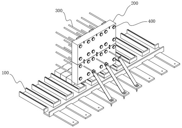
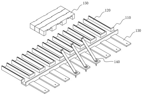
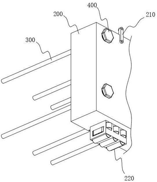
[0049] This embodiment specifically discloses the rail frame 100, please refer to Figure 1-Figure 3As shown, the rail frame 100 includes a main rail 110, one side of the main rail 110 is equidistantly arranged with a plurality of side rails 120 along the length direction, a plurality of sliders 220 are arranged at the bottom of the formwork 200, and the tops of the main rail 110 and the side rails 120 are both A top groove is provided, and the slider 220 is slidably connected with the top groove, wherein:
[0050] The top groove of the main rail 110 is used for laterally limiting the slider 220;
[0051] The top groove of the side rail 120 is used for longitudinally limiting the slider 220;
[0052] The distance between two adjacent sliders 220 is equal to the distance between two adjacent side rails 120 , the main purpose of which is to ensure that the sliders 220 can slide into the corresponding side rails 120 at the same time.
[0053] working principle:
[0054] First ...
Embodiment 2
[0060] This embodiment specifically discloses the anchoring assembly 400. The template 200 is provided with a connecting groove 230, and the reinforcing rib 300 is inserted into the corresponding connecting groove 230. An anchoring groove 231 is provided at the outer end of the connecting groove 230. The anchoring assembly 400 is set In anchor slot 231, see Figure 4 As shown, the anchoring assembly 400 includes an anchoring plate 410. The anchoring plate 410 has a bent structure and is arranged in an annular array in the anchoring groove 231. The anchoring assembly 400 also includes an expansion head 420, and the outside of the expansion head 420 is provided with Extrude the screw rod 430, and the extruded screw rod 430 is threadedly connected with the anchor groove 231, wherein:
[0061] An adapter frame 411 is arranged outside the anchor plate 410, and the anchor plate 410 is rotationally connected to the inner wall of the anchor groove 231 through the adapter frame 411, an...
Embodiment 3
[0068] Considering the setting of the main track 110 and the side track 120, it is necessary to isolate them when building the wall, otherwise the concrete will be in contact with the main track 110 and the side track 120, and it will be inconvenient to take it out later, please refer to figure 2 As shown, the top of the side rail 120 is provided with a bottom plate 150, see Figure 7 As shown, the bottom of the base plate 150 is provided with slots corresponding to the positions of the side rails 120. During use, the slots at the bottom of the base plate 150 are placed on the side rails 120, and the isolation of the side rails 120 is achieved by assembling multiple base plates 150.
[0069] In addition, in order to improve the integrity of the assembly of the bottom plate 150, one side of the bottom plate 150 is provided with a clamping plate 151, and the other side is provided with a clamping groove 152, please refer to Figure 8 As shown, a slot 250 is provided on the inne...
PUM
 Abstract
Description
Claims
Application Information
 - R&D
- Intellectual Property
- Life Sciences
- Materials
- Tech Scout
- Unparalleled Data Quality
- Higher Quality Content
- 60% Fewer Hallucinations
Browse by: Latest US Patents, China's latest patents, Technical Efficacy Thesaurus, Application Domain, Technology Topic, Popular Technical Reports.
© 2025 PatSnap. All rights reserved.Legal|Privacy policy|Modern Slavery Act Transparency Statement|Sitemap|About US| Contact US: help@patsnap.com


