Image display apparatus, method and program based on rigid body dynamics

Active Publication Date: 2009-10-27
CRITERION SOFTWARE
View PDF0 Cites 30 Cited by
  • Summary
  • Abstract
  • Description
  • Claims
  • Application Information

AI Technical Summary

Benefits of technology

[0033]In known approaches, the second derivative was held to be zero. However, the method according to the invention provides much faster calculation.
[0034]The method may cause the computer to carry out the further step of displaying an image of the objects at their calculated positions on the computer display screen, so that the display shows the objects on the screen using physical laws to simulate their motion.
[0043]The dependence of the frictional force on the normal force can be replaced by a novel approximation in which the friction, dynamic or static, is not dependent on the normal force. This force then corresponds to a simple bounded multiplier, i.e. a force that can have up to a predetermined value. Thus the force exactly fits the model used in any event in which the constraint forces Lagrange multipliers have maximum values; friction in the model is equivalent to another bounded constraint force. Thus making this approximation substantially simplifies the inclusion of friction in the model.
[0048]The friction model taken leads to a symmetric positive definite linear complementarity problem, in which the only friction conditions are simple inequalities. This allows the use of the much more efficient Murty algorithm that the less useful Lemke algorithm.

Problems solved by technology

Thus, such an approach cannot be used where the scenes are not wholly scripted, which makes the approach unsuitable for simulations and computer games in which the user can carry out actions not predicted by the programmer.
The existence of constraints makes the problem much more difficult to solve than a simple application of Newton's laws of motion.
A number of prior approaches have been presented but these have not proven wholly successful.
However, there are difficulties with these approaches.
Firstly, the known methods use a large number of variables, using nearly doubling the number of variables (because of the Lagrange multipliers) to describe the system, which results in them being eight times more computationally intensive than an equivalent system without constraints.
Thus, the prior art methods tend to be highly inefficient.
Secondly, the known methods use differential algebraic equations that are numerically rather stiff.
Simple methods for solving such equations are rather unstable.
Thirdly, it is not known how to efficiently incorporate friction into such systems.
The disadvantage of the approach is that the model involves solving a particular class of linear complementarity problem which has a structure such that not all algorithms are suitable.
Anitescu and Trinkle used the Lemke algorithm but this is inefficient and prone to large errors.
A fourth difficulty with prior art approaches is that the constraints are generated automatically; such constraints need not be not independent of one another which results in the system being degenerate.
Geometric analysis software that performs collision detection cannot check whether all the constraints are truly independent of each other, and only during simulation can it be determined that some constraints are redundant.
Such degeneracy can cause real problems for the simulations, especially in the case of collision detection which checks for proximity of pairs of objects, whereas the constraint degeneracy only appears at the system level including all the rigid bodies in the system.
Fifthly, known systems do not cope well with stiffness, i.e. rigid spring-like systems and compliant elements.
The only tractable solutions ignore contact and friction altogether, which makes them unsuitable for analysis of arbitrary physical systems.
The method can fail where the matrix is positive semi-definite.

Method used


Image

  • Image display apparatus, method and program based on rigid body dynamics
  • Image display apparatus, method and program based on rigid body dynamics
  • Image display apparatus, method and program based on rigid body dynamics

Examples


Embodiment Construction

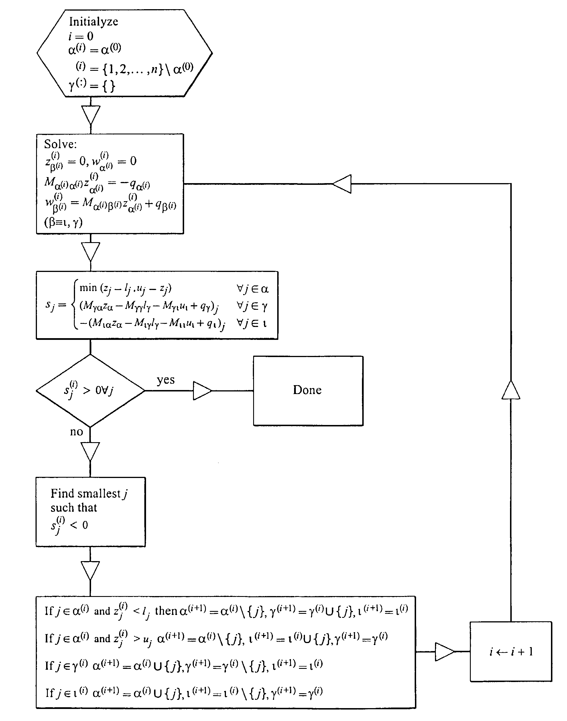
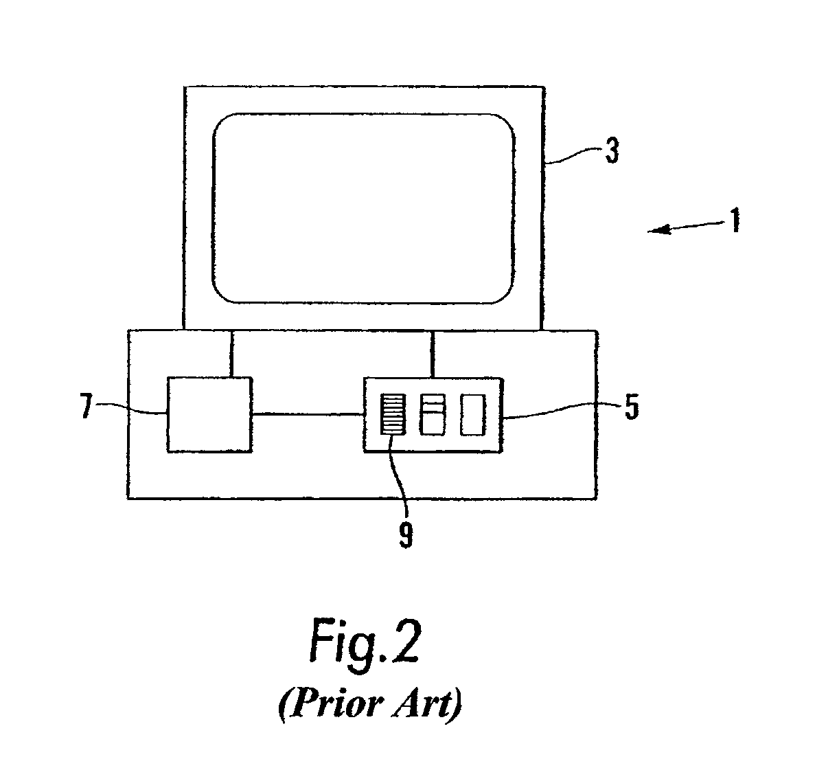
[0059]The implementation of the invention that will be described includes a computer system 1 having a display 3, a memory 5 and a processor. The computer system has software 9 loaded into the computer memory to allow the computer system to display a simulation of the real physical world on the display 3. The display 3 may be a conventional computer display screen, for example an Liquid Crystal Display (LCD) screen or a Cathode Ray Tube (CRT) screen, or the display 3 may be a less conventional display type such as virtual reality goggles or multiple screens of a coin operated video game, of the type installed in public places.

[0060]A physical system which has n rigid bodies is modelled. The ith body has a mass mi, and a position vector p which has s seven coordinates, three to define the position of the rigid body and four being the Euler parameters of the body defining its orientation. Each body also has velocity vector v which has six coordinates, three being the three components ...


PUM


Abstract

An image display system and method that use physical models to produce a realistic display of a scene are disclosed. The image display method involves operating a computer having a display screen, a memory and a processing unit for simulating the motion of objects and displaying the results on the display screen. The method includes the steps of storing in the memory position and velocity parameters which define an initial state of a model system having a plurality of bodies, storing in the memory parameters which define at least one constraint function constraining the motion of the bodies in the model system, and calculating in the processor the position and velocity parameters which define the state of the system after a predetermined time step based on rigid body dynamics, including carrying out a semi-implicit integration step subject to the constraints, to determine the velocity after the step, including determining the constraint forces that act to keep the system in compliance with the constraints by ensuring that the first derivative of the constraint function is zero.

Description

BACKGROUND OF THE INVENTION[0001]The invention relates to an image display system and method, and in particular to an image display system that uses physical dynamic models to produce a realistic display of a scene.[0002]It is becoming increasingly useful to display scenes on computer displays that represent the real world. Such scenes may occur in virtual reality devices, simulators and computer games.[0003]One way of providing such scenes is to film images and to display the recorded images on the display. However, this approach requires that the content of the scene is predetermined and appropriate film sequences created and pre-stored in the computer. Thus, such an approach cannot be used where the scenes are not wholly scripted, which makes the approach unsuitable for simulations and computer games in which the user can carry out actions not predicted by the programmer.[0004]An alternative approach uses a simulation of rigid body dynamics to allow scenes including such objects ...

Claims


Application Information

Patent Timeline
IPC IPC(8): G06F17/10G06G7/48G06F19/00G06F17/50G06T13/20
CPCG06F17/5009A63F2300/64G06F2217/06A63F2300/643G06F2111/04G06F30/20
Inventor SMITH, RUSSELL LEIGHCLAUDE, LACOURSIERE
Owner CRITERION SOFTWARE
Why Eureka
Try Eureka