Air conditioning system
a technology of air conditioning system and air intake, which is applied in the direction of domestic cooling apparatus, lighting and heating apparatus, refrigeration components, etc., can solve the problems of suction loss, energy loss, energy loss, etc., and achieve the effect of energy loss and potential work loss
- Summary
- Abstract
- Description
- Claims
- Application Information
AI Technical Summary
Benefits of technology
Problems solved by technology
Method used
Image
Examples
second embodiment
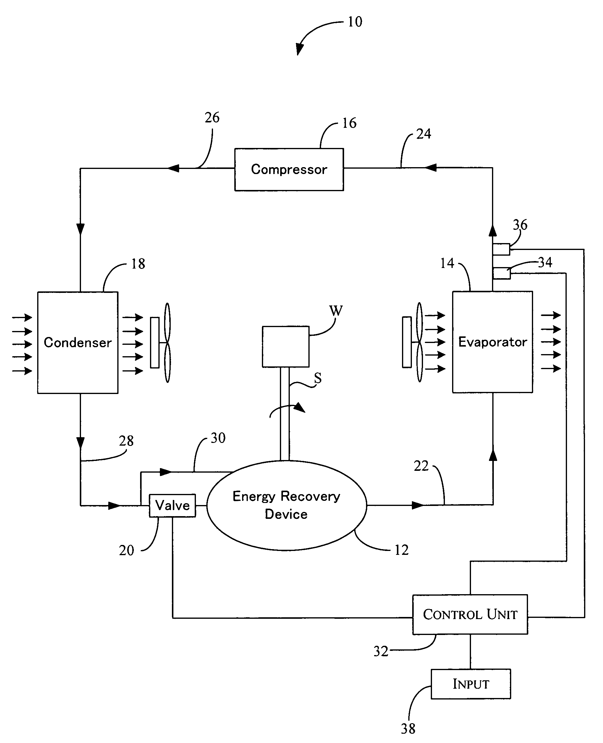
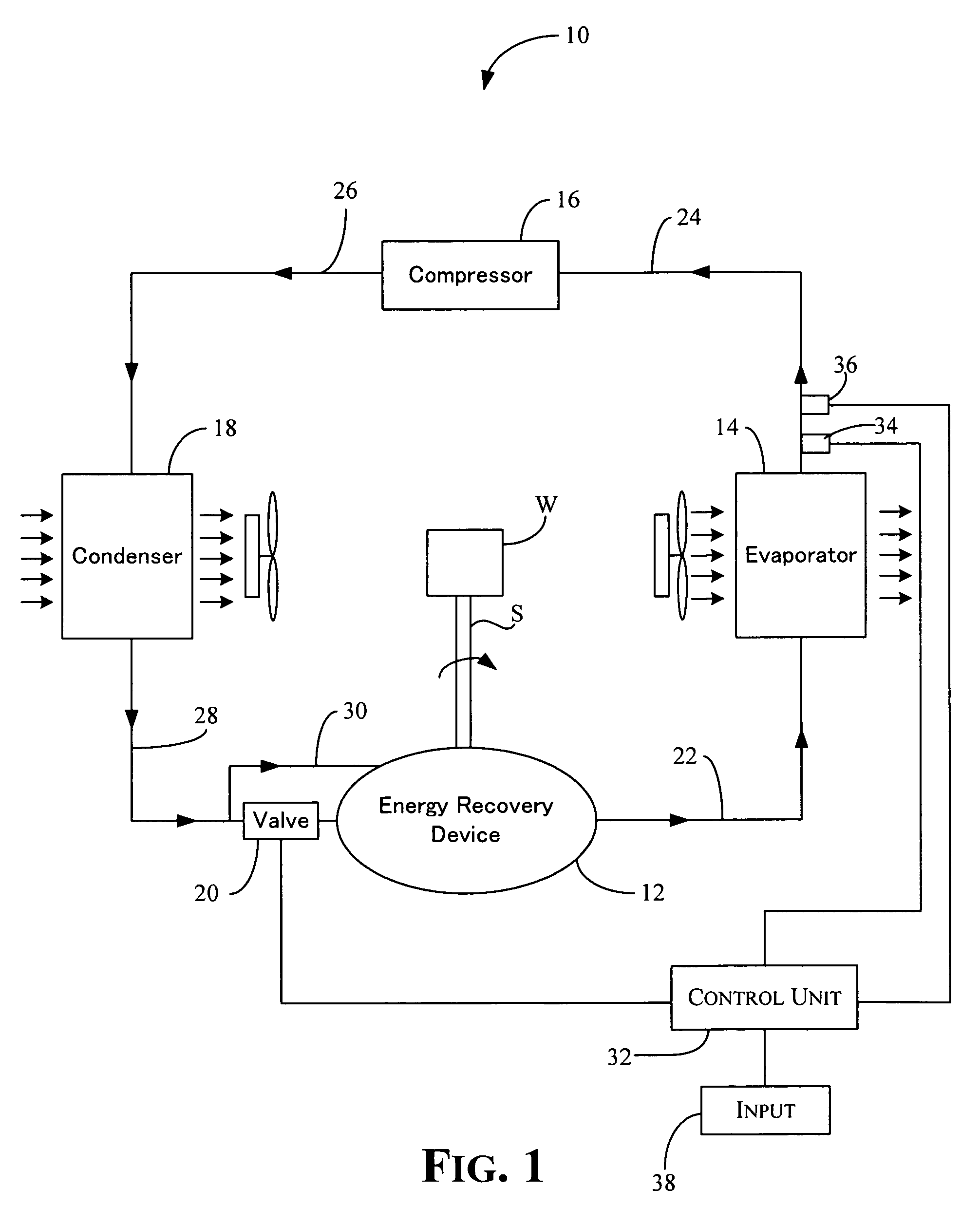
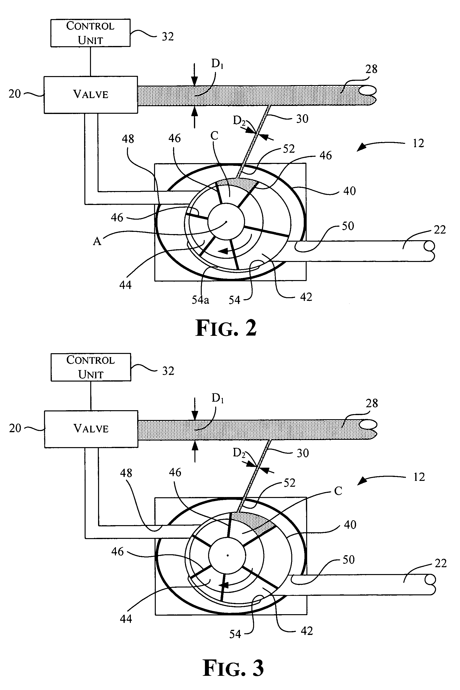
[0052]Referring now to FIG. 5, an energy recovery device 212 of an air conditioning system 210 shown in accordance with a second embodiment will now be explained. In view of the similarity between the first and second embodiments, the parts of the second embodiment that are identical to the parts of the first embodiment will be given the same reference numerals as the parts of the first embodiment. Moreover, the descriptions of the parts of the second embodiment that are identical to the parts of the first embodiment may be omitted for the sake of brevity. The parts of the second embodiment that differ from the parts of the first embodiment will be indicated with a single prime (′) or be given a new reference numeral.
[0053]In the second embodiment, the energy recovery device 212 includes many of the same features as in the first embodiment, such as the housing 40, the expansion chamber 42, the rotor 44, the vanes 46, the inlet 48, the outlet 50 and the bypass port 52. The energy rec...
third embodiment
[0055]Referring now to FIG. 6, an energy recovery device 312 of an air conditioning system 310 shown in accordance with a third embodiment will now be explained. In view of the similarity between the first, second and third embodiments, the parts of the third embodiment that are identical to the parts of the first and / or second embodiments will be given the same reference numerals as the parts of the first and / or second embodiments. Moreover, the descriptions of the parts of the third embodiment that are identical to the parts of the first and / or second embodiment may be omitted for the sake of brevity. The parts of the third embodiment that differ from the parts of the first embodiment will be indicated with a double prime (″) or be given a new reference numeral.
[0056]In the third embodiment, the energy recovery device 312 includes many of the same features as in the first and second embodiments, such as the housing 40, the expansion chamber 42, the inlet 48, the outlet 50 and the ...
fourth embodiment
[0059]Referring now to FIG. 7, a portion of an air conditioning system 410 shown in accordance with a fourth embodiment will now be explained. In view of the similarity between the first and fourth embodiments, the parts of the fourth embodiment that are identical to the parts of the first embodiment will be given the same reference numerals as the parts of the first embodiment. Moreover, the descriptions of the parts of the fourth embodiment that are identical to the parts of the first embodiment may be omitted for the sake of brevity. The parts of the fourth embodiment that differ from the parts of the first embodiment will be indicated a new reference numeral.
[0060]In the fourth embodiment, the control unit 32 of the first embodiment has been replaced with a simple relay 80 for controlling opening and closing of the valve 20. The relay 80 is connected to a pressure sensor 82 that is installed in either the low-pressure line 22 or the low-pressure line 24 (not shown in FIG. 7). Wh...
PUM
 Abstract
Description
Claims
Application Information
 - R&D Engineer
- R&D Manager
- IP Professional
- Industry Leading Data Capabilities
- Powerful AI technology
- Patent DNA Extraction
Browse by: Latest US Patents, China's latest patents, Technical Efficacy Thesaurus, Application Domain, Technology Topic, Popular Technical Reports.
© 2024 PatSnap. All rights reserved.Legal|Privacy policy|Modern Slavery Act Transparency Statement|Sitemap|About US| Contact US: help@patsnap.com


