Speech decoder, speech decoding method, program and storage media to improve voice clarity by emphasizing voice tract characteristics using estimated formants
a speech decoding and voice tract technology, applied in the field of communication devices, can solve the problems of degraded clarity, remote users are faced with the problem of further degradation of voice quality, and difficulty in hearing the received voice impaired, so as to improve the output voice clarity
- Summary
- Abstract
- Description
- Claims
- Application Information
AI Technical Summary
Benefits of technology
Problems solved by technology
Method used
Image
Examples
first embodiment
[0107]FIG. 3 shows a structural block diagram of a speech decoder 40 according to a
[0108]In FIG. 3, components that are approximately the same in configuration as those of the speech decoder 20 shown by FIG. 2 are assigned the same component numbers.
[0109]Note that the CELP method is used for the voice coding method in the present embodiment, but it is not limited as such and, rather, any voice coding method in the analysis-synthesis system may be applied.
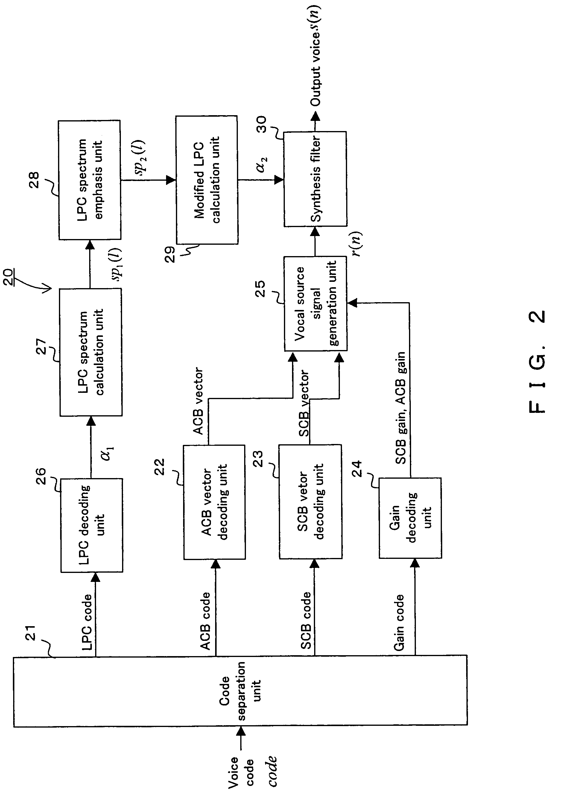
[0110]First, the code separation unit 21 separates the voice code code into LPC, ACB, SCB codes and a gain code.
[0111]The ACB vector decoding unit 22 decodes the above noted ACB code to obtain the ACB vectors p(n), where 0≦n≦N, and N is the frame length of the coding method. The SCB vector decoding unit 23 decodes the above noted SCB code to obtain the SCB vectors c(n), where 0≦n≦N. The gain decoding unit 24 decodes the above noted gain code to obtain the ACB gain gp and the SCB gain gc.
[0112]The vocal source signal generation unit...
second embodiment
[0145]FIG. 7 shows a structural block diagram of a speech decoder 50 according to a
[0146]In the configuration shown by FIG. 7, components that are approximately the same as those of the speech decoder 40 shown by FIG. 3 are assigned the same component numbers, and the details different from the first embodiment are described in the following.
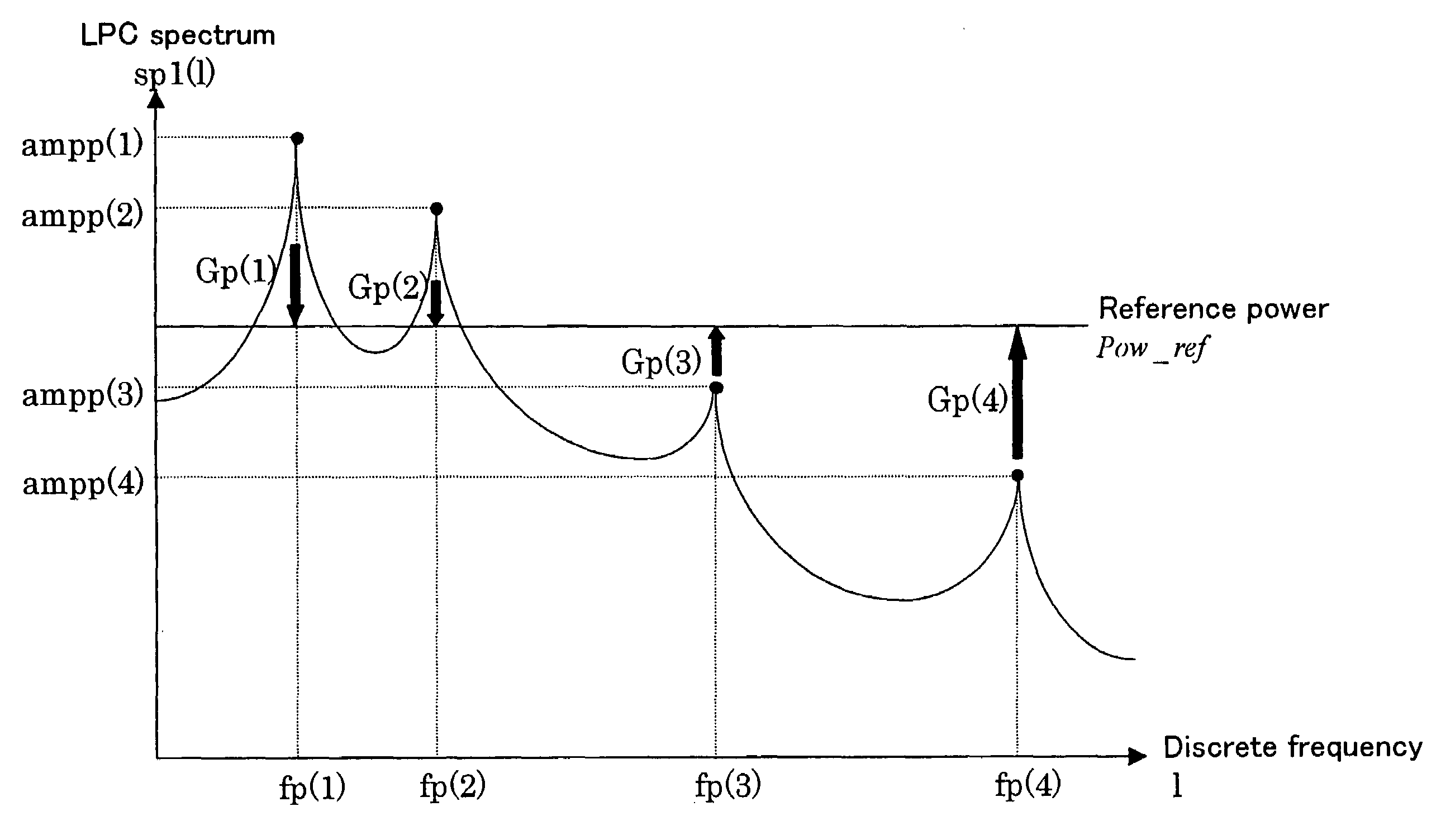
[0147]The second embodiment is characterized by attenuating anti-formants whose amplitudes take minimum values, in addition to emphasizing formants to emphasize the difference between formants and anti-formants. Note that the present embodiment assumes that an anti-formant only exists between two adjacent formants in the following description, but it is not limited as such and rather it is possible to apply the present embodiment to the case where an anti-formant exists in a lower frequency than the lowest order formant or in a higher frequency than the highest order formant.
[0148]A speech decoder 50 shown by FIG. 7 comprises a formant / anti-form...
third embodiment
[0173]FIG. 10 shows a structural block diagram of a speech decoder 60 according to a
[0174]In the configuration shown by FIG. 10, components that are approximately the same as those of the speech decoder 3 shown by FIG. 40 are assigned the same component numbers, and the following description is of the parts different from those of the first embodiment.
[0175]The third embodiment is characterized by a configuration for applying a pitch emphasis on a vocal source signal in addition to that of the first embodiment, that is, by comprising a pitch emphasis filter configuration unit 62 and a pitch emphasis unit 63. Furthermore, an ACB vector decoding unit 61 not only decodes the ACB code to obtain ACB vectors p(n), where 0≦n≦N, but also obtain the integer part T of pitch lag from the ACB code to output to the pitch emphasis filter configuration unit 62.
[0176]While the method for a pitch emphasis is discretionary, there is for example the following method.
[0177]First, the pitch emphasis fil...
PUM
 Abstract
Description
Claims
Application Information
 - R&D
- Intellectual Property
- Life Sciences
- Materials
- Tech Scout
- Unparalleled Data Quality
- Higher Quality Content
- 60% Fewer Hallucinations
Browse by: Latest US Patents, China's latest patents, Technical Efficacy Thesaurus, Application Domain, Technology Topic, Popular Technical Reports.
© 2025 PatSnap. All rights reserved.Legal|Privacy policy|Modern Slavery Act Transparency Statement|Sitemap|About US| Contact US: help@patsnap.com


