Programmable, multi-spectral, image-capture environment

Active Publication Date: 2009-10-13
CANFIELD SCI
View PDF21 Cites 31 Cited by
  • Summary
  • Abstract
  • Description
  • Claims
  • Application Information

AI Technical Summary

Benefits of technology

[0016]It is therefore an object of the present invention to precisely create and shape the lighting environment during a single-image exposure consisting of a plurality of different spatially-separated flash or pulsed-light source to be fired in a preprogrammed sequence, potentially complemented with fixed light sources, wherein the spectral content, intensity, and duration are specified for each lighting event of the specified sequence.
[0017]It is another object of the invention to provide for the customization of lighting characteristics to enhance the specific attributes of the subject to be analyzed, permitting the selective use of xenon flash or other pulsed-light source potentially complemented with one or more continuous-light sources and optical / spectral processing such as wavelength band filtering (UV, infrared, etc.), and light polarity (linear, cross, parallel, or circular). Further enhancement of the attribute is possible through control of the lighting directionality, achieved by selecting the appropriately positioned light source, and specifying its firing sequence, and output intensity to achieve the desired effect ranging from very soft indirect, and diffused to hard and directional lighting.
[0018]It is a further object of the invention to provide a single photometric sensor to quantitatively meter and control the output of each flash / light source, thereby ensuring consistent light metering amongst the various sources, eliminating the potential for any differences due to inter-sensor variability, and providing a cost effective means over the alternative implementation of separate sources having a dedicated photometric sensor associated with each flash / light source that would implement a totally non-image-related metering mode and potentially cross contaminate each other.
[0019]It is another object of the invention to provide a single photometric sensor disposed near the subject being photographed, thereby ensuring the accurate measurement of the actual light that will be received at the subject as opposed to reflected light that has been the prior art (whether that light is measured by the flash unit itself or in conjunction with a camera's Through The Lens [TTL] metering system).
[0020]It is a further object of the invention to support rapid, burst image capture, wherein the lighting characteristics for each image in the capture sequence can be created and shaped according to a programmable shooting template, thereby helping to minimize subject movement image-to-image in the capture sequence, critical for cross image-comparison purposes.

Problems solved by technology

These calculations are very complicated because various settings (illumination angle setting, subject distance setting, guide number, etc.) are generally different between / amongst the other flash devices.

Method used


Image

  • Programmable, multi-spectral, image-capture environment
  • Programmable, multi-spectral, image-capture environment
  • Programmable, multi-spectral, image-capture environment

Examples


Embodiment Construction

[0029]The present invention provides an apparatus and method for creating a programmable, multi-spectral flash environment.

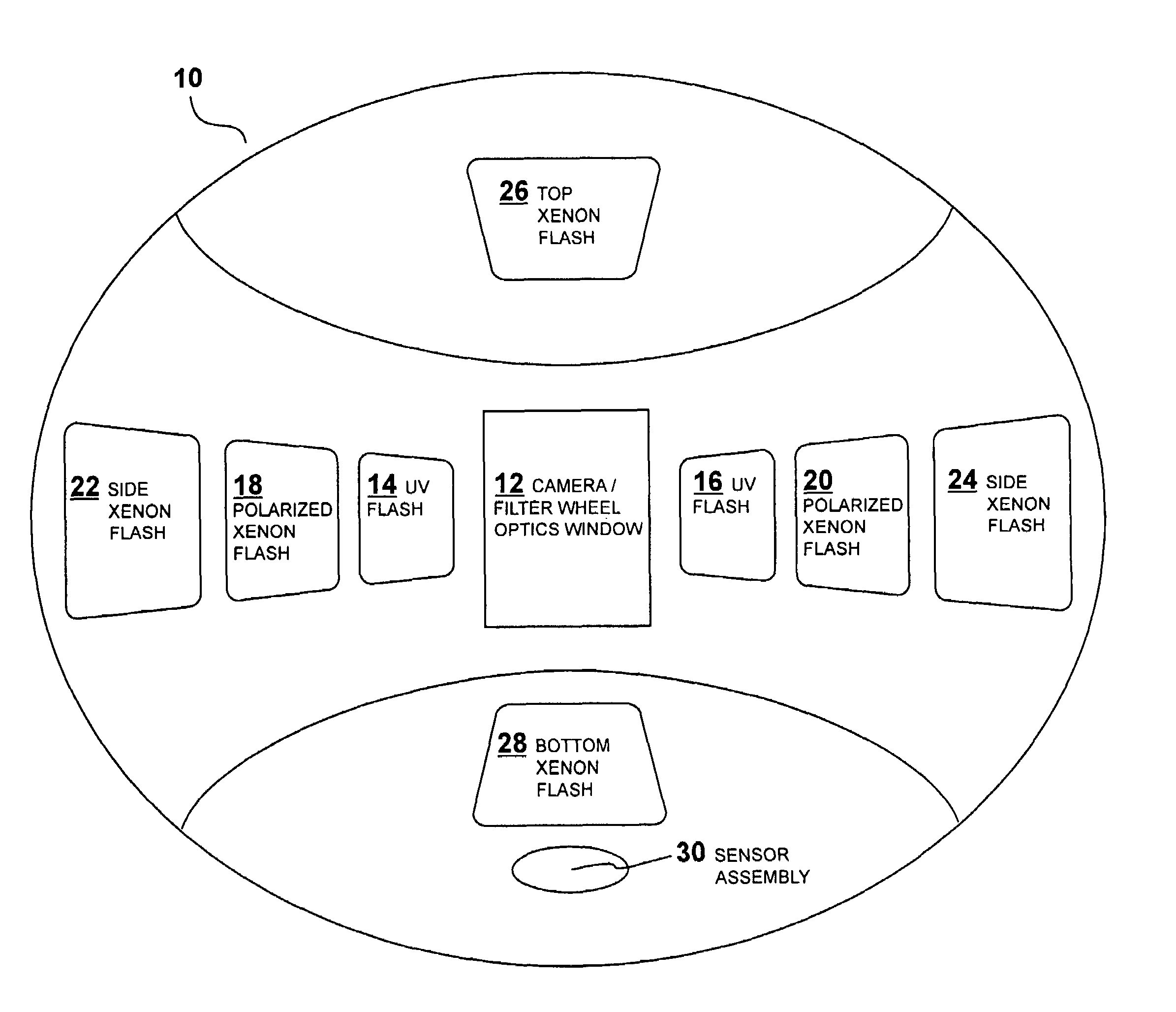
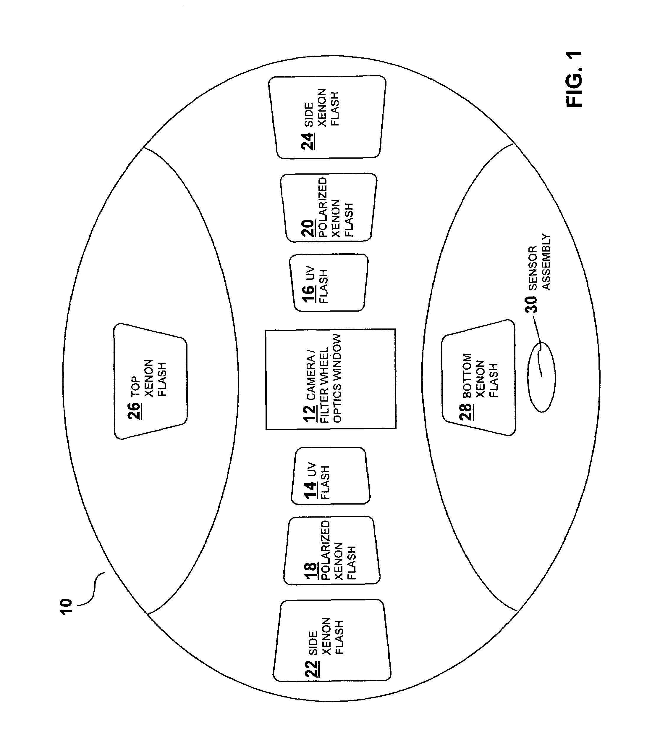
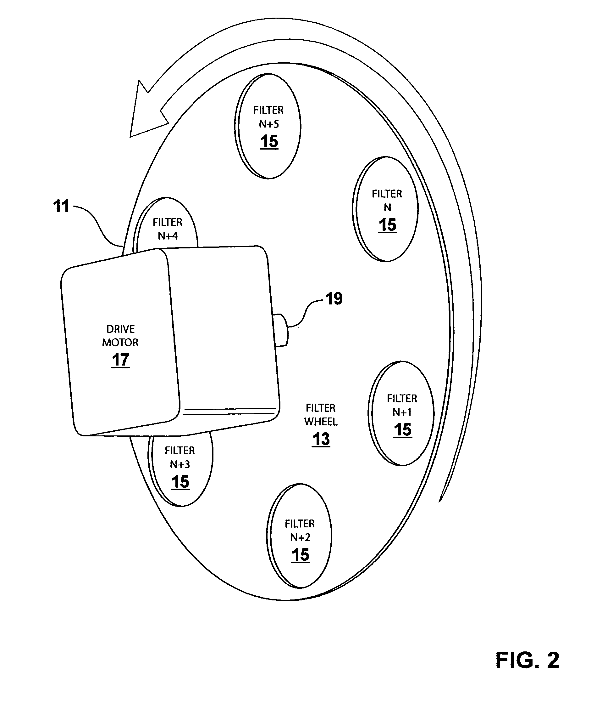
[0030]FIG. 1 illustrates one embodiment of the flash environment 10 that is particularly suited for medical and cosmetic facial photography. The flash environment 10 may include a centrally-mounted camera optics window 12 which, as is well-known to those skilled in the art, will have the camera lens and filter mechanism, such as a filter wheel, located directly behind it. Referring briefly to FIG. 2, a filter wheel 11 is illustrated. The filter wheel 11 includes a wheel 13 having a plurality of filters 15 disposed about its periphery. The wheel 13 is rotated by a drive motor 17 connected to the center of the wheel 13 by a drive shalt 19. Referring back to FIG. 1, a pair of ultraviolet flashes 14,16, using xenon tubes covered by ultraviolet filters, may be located on either side of the camera optics window 12. Continuing to move outward from either side of the ca...


PUM


Abstract

A multi-flash photography system provides a dynamically-configurable lighting environment for a single exposure that is created and shaped through the sequentially firing of various light sources with different lighting characteristics controlled in accordance with both a programmed template specifying the flash type, position, firing order, and output intensity, as well as optical processing requirements such as filtering, polarizing, etc., and a shared photometric detector located sufficiently close to the subject being photographed to ensure that the light seen by the detector is substantially the same as the light received at the subject.

Description

CROSS REFERENCE TO RELATED APPLICATION[0001]This application claims the benefit of U.S. Provisional Patent Application No. 60 / 636,197, filed Dec. 15, 2004.BACKGROUND OF THE INVENTION[0002]1. Field of the Invention[0003]The present invention relates to multi-flash photography and other image capture systems. More specifically, the invention provides a photography system wherein the lighting environment for a single exposure is created and shaped through the sequentially firing of various flash devices with different lighting characteristics controlled in accordance with both a programmed template and a shared photometric detector located near the subject being photographed.[0004]2. Description of the Related Art[0005]Various types of multi-flash photography systems in which the amount of light of the main flash unit discharge is controlled in accordance with photometric reading taken from reflected light from either the entire or different areas of the subject (or a scene / object) at ...

Claims


Application Information

Patent Timeline
IPC IPC(8): G03B15/03A61B6/00H04N5/222
CPCA61B5/441G03B15/03G03B7/16A61B5/0059G03B2215/0557
Inventor VIAUD, GEORGEBUDRIS, KENCANFIELD, DOUGDASILVA, DENNISDORNBUSCH, JIMROBINSON, JOHN
Owner CANFIELD SCI
Why Eureka
Try Eureka