Apparatus for providing visual indication of engagement of a drive received within a drive cage

Active Publication Date: 2009-10-06
NETWORK APPLIANCE INC
View PDF28 Cites 13 Cited by
  • Summary
  • Abstract
  • Description
  • Claims
  • Application Information

AI Technical Summary

Benefits of technology

[0006]Providing an easy and reliable way for an operator to identify an improperly seated drive, without adding significant cost or complexity to the storage system enclosure is paramount. The attachment or integration of an indicator directly to the drive, the drive cage or the carrier mounted to the drive may provide an operator of the storage system enclosure a simple, low-tech, low-cost method for identifying an improperly seated drive. The drive, whether attached with a carrier or not, has a seated position which indicates that it has been correctly engaged with the drive cage. This allows for communication between the drive and the drive cage, usually through a drive cage controller. Communication may be enabled with an operator who is attempting to utilize the drive through an information handling system interfaced with the drive cage controller. The indicator is of a contrasting color to what it is attached to or integrated with and may be visually ascertainable when the drive is not properly seated in the drive cage and, thus, not correctly engaged.

Problems solved by technology

An operator may visually ascertain the indicator when the drive is not properly seated in the drive cage and, thus, an operator would not see the indicator when the drive is properly seated.

Method used


Image

  • Apparatus for providing visual indication of engagement of a drive received within a drive cage
  • Apparatus for providing visual indication of engagement of a drive received within a drive cage
  • Apparatus for providing visual indication of engagement of a drive received within a drive cage

Examples


embodiment 300

[0041]FIG. 3 illustrates a RAID storage shelf 310 including a communication port adapter 320 in embodiment 300. RAID storage shelf 310 has an internal bottom side, internal top side, internal right side and internal back side. The communication port adapter is included on the internal back side in a location, which will enable a coupling of the communication port adapter on the RDA 100 with the one on RAID storage shelf 310. Contained upon the internal bottom side of RAID storage shelf 310 is an apparatus for providing insertion slots of individual RDA 100 units. In the present embodiment the apparatus are individual runner boards 330, which function to delineate the separate seating positions. The inside surface of RAID storage shelf 310 is of a tactile material such as steel. This protects the devices within and provides a smooth insertion surface.

[0042]The communication port adapter may include a parallel port, special connector and other such mechanisms of communicative coupling...

embodiment 500

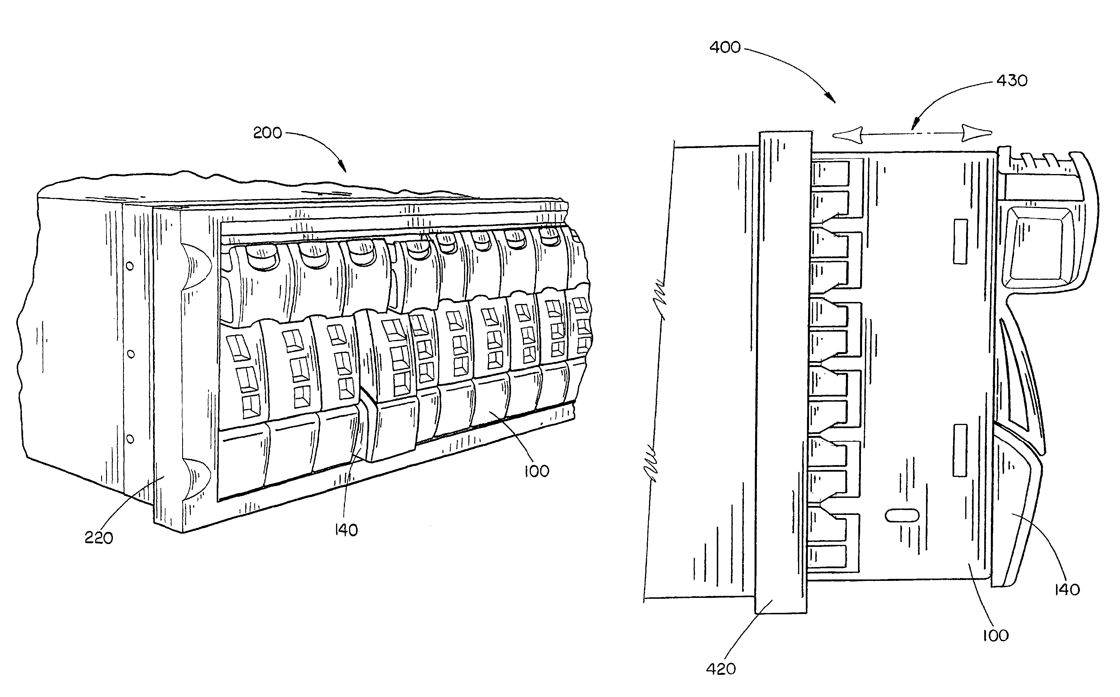
[0047]An improperly seated RDA 100 is shown in FIGS. 5A and 5B. The embodiment 500 of the present invention shows RDA 100 is incorrectly seated, in two orientations, within a RAID storage shelf 520. Each illustration depicts the exposed left side of RDA 100 with indicator 140 attached.

[0048]Illustration of FIG. 5A shows RDA 100 in a nearly fully exposed seating position within RAID storage shelf 520. Phantom lines indicate the positioning of RDA 100 with respect to RAID storage shelf 520. In this position indicator 140 is visually ascertained almost in its entirety. Thus, an operator may be visually capable of identifying that RDA 100 is improperly seated within RAID storage shelf 520. In a RAID storage shelf with a throw lever (described in the discussion of FIG. 2) a user may ascertain that the throw lever has not exhausted its rotational movement capabilities. As such there remains some capacity in this system for RDA 100 to make some linear movement either by rotationally engagi...

embodiment 600

[0050]Referring to FIGS. 6A and 6B a properly seated and engaged RDA 100 is shown. Embodiment 600 of the present invention shows that RDA 100 (as shown in FIGS. 1A-1D) is correctly engaged and seated within a RAID storage shelf 620 (as described in FIGS. 2 and 3). The illustration of FIG. 6A shows RAID storage shelf 620 in a horizontal position. RAID storage shelf 620 contains multiple RDA 100 units properly seated. RDA 100 units are flush across the front with the handle of the top area of the front portion protruding beyond the edge of RAID storage shelf 620. Indicator 140 is not visible on any RDA 100 units. In this positioning of RDA 100 units it may be recognized that they are properly seated and engaged, thus, communicatively coupled with RAID storage shelf 620 and therefore, may be communicatively connected with a user interface and available to the user.

[0051]The illustration of FIG. 6B shows RAID storage shelf 620 in a vertical position. RDA 100 units are properly seated an...


PUM


Abstract

An apparatus for providing the visual indication of engagement of a drive received within a drive cage includes an indicator attached to a carrier mounted on a drive received within, a drive cage. The drive cage may be a redundant array of independent disks storage shelf and the drive may be a hard disc drive suitable for being received in the drive cage. Further, the indicator may be attached to at least one of the drive and the drive cage and provides visual indication of when the drive is properly seated in the drive cage. The indicator is at least one of a contrasting color, symbol, pattern, portrait and the like, to what it is attached to.

Description

CROSS REFERENCE TO RELATED APPLICATION[0001]The present application claims priority under 35 U.S.C. §119 to U.S. Provisional Application Ser. No. 60 / 370,864 filed Apr. 8, 2002, which is herein incorporated by reference in its entirety.FIELD OF THE INVENTION[0002]The present invention generally relates to the field of storage system enclosures and particularly to an apparatus for providing visual indication of engagement of a drive received within a drive cage, such as a hard disk drive within a redundant array of independent disks storage shelf, or the like.BACKGROUND OF THE INVENTION[0003]Though storage system enclosures may become more and more powerful, users are demanding a higher level of “user friendliness”. For instance, components of storage system enclosures may be mounted with a carrier to make transporting them easier. Aesthetically pleasing color schemes have had a significant impact upon these systems. This coloring has positively impacted the sales of these systems but...

Claims


Application Information

Patent Timeline
IPC IPC(8): H05K7/20
CPCH05K7/1425G11B33/128
Inventor MOISSON, MARC
Owner NETWORK APPLIANCE INC
Why Eureka
Try Eureka