Flush cap with shut-off for sprinker head

Inactive Publication Date: 2006-03-09
K RAIN MFG
View PDF16 Cites 14 Cited by
  • Summary
  • Abstract
  • Description
  • Claims
  • Application Information

AI Technical Summary

Benefits of technology

[0011] The present invention seeks to satisfy this need by providing a flush cap assembly which includes a mechanism to shut off the water to individual spray heads and to reliably prevent backflow of debris through the shut off flush cap, as well as a method of preparing a sprinkler system for operation using such a flush cap assembly.
[0013] Flush caps according to the invention provide improved functionality without adding significant cost, and the associated method permits more efficient, and, in some instances, faster preparation of the system for use.
[0014] The invention has several specific advantages over conventional flush caps. First, the shut off mechanism according to the invention allows the installer to shut off each spray head after sufficient water has flowed through that respective spray head. By enabling the installer to selectively stop the water flow through individual spray heads, further flushing of other spray heads can continue to be flushed without further flooding around the spray heads that have been shut off.
[0015] A second advantage provided by the invention is that when the installer shuts off selected spray heads, water flow to the other spray heads increases, which results in an increased flow rate of water through the other spray heads to thereby flush the system more effectively.

Problems solved by technology

Once this has been done, the piping and spray heads must be flushed before the spray nozzles are installed to remove dirt and debris which accumulated in the system during installation, or the spray nozzles may become unobstructed when the system is placed in operation.
For one thing, it is difficult to reliably seal the flush openings after the flushing process is completed.
As a result, there is a risk of debris re-entering the spray heads, particularly, since the flush water usually pools around the spray heads.
Providing a reliable closure often entails increased cost and complexity in an item which is generally not reusable.
Another problem is that conventional flush caps lack a way to selectively close an individual flush cap at a particular location in the system when further flushing of the spray head at that location is not needed, but other spray heads require further flushing.

Method used


Image

  • Flush cap with shut-off for sprinker head
  • Flush cap with shut-off for sprinker head
  • Flush cap with shut-off for sprinker head

Examples


Embodiment Construction

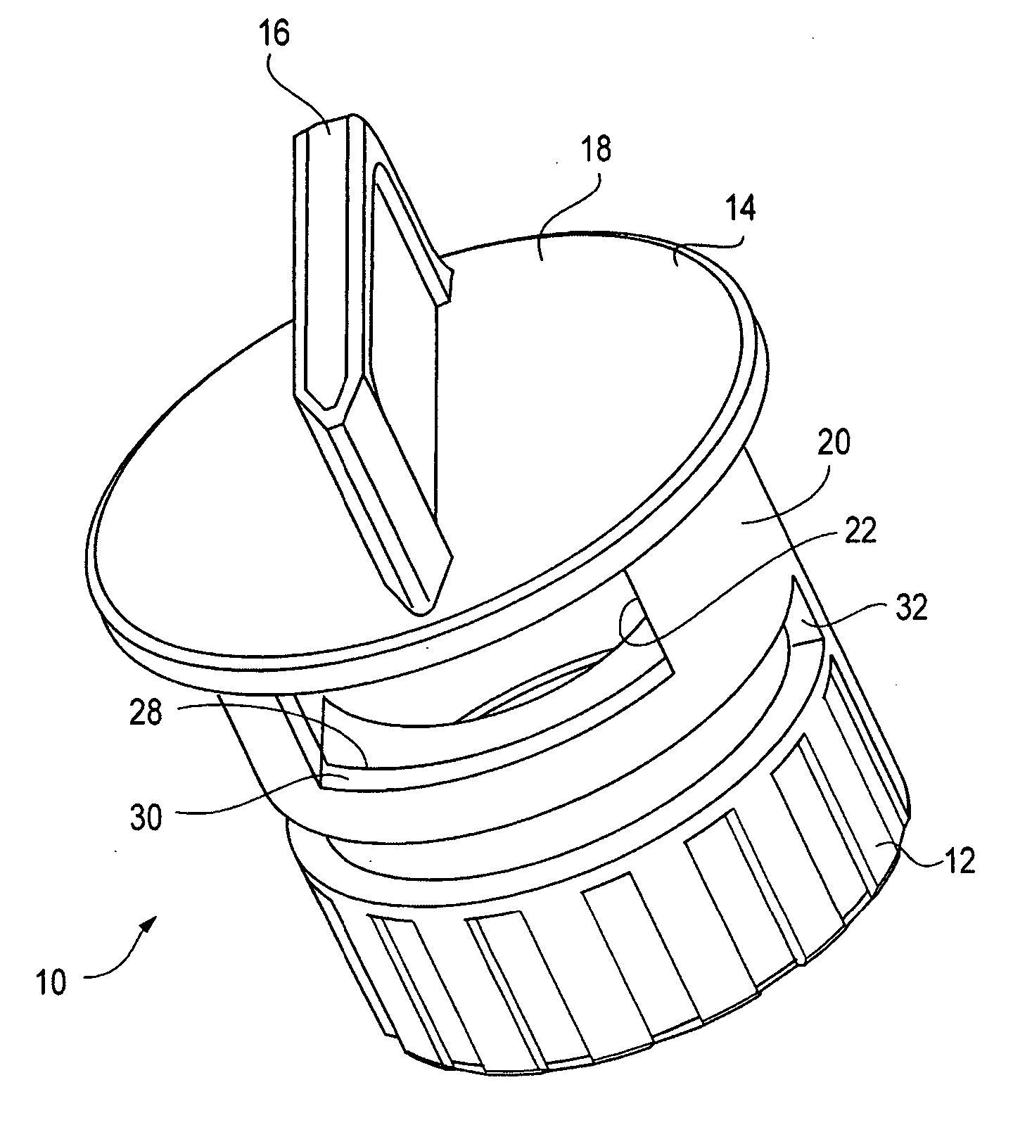
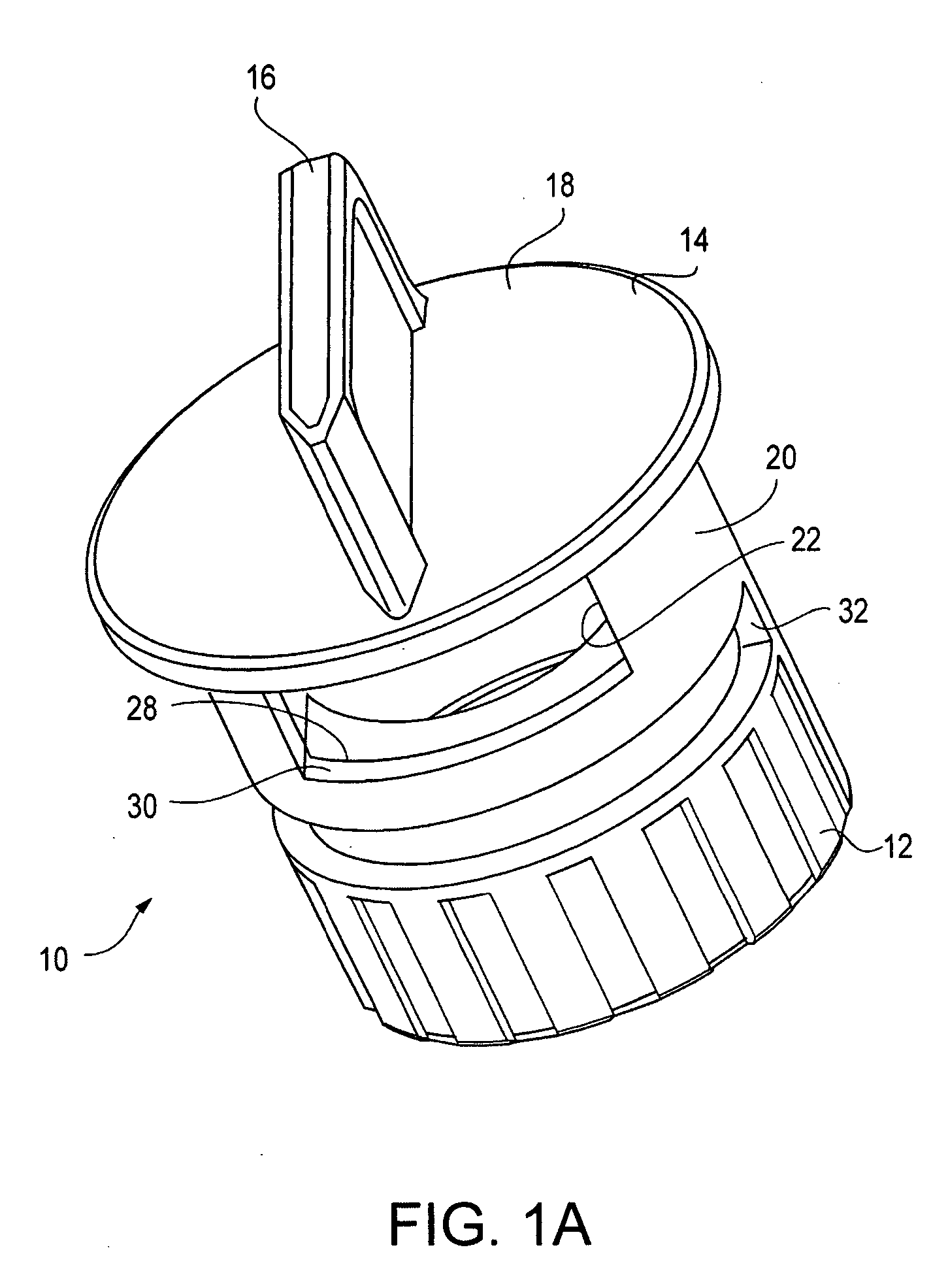
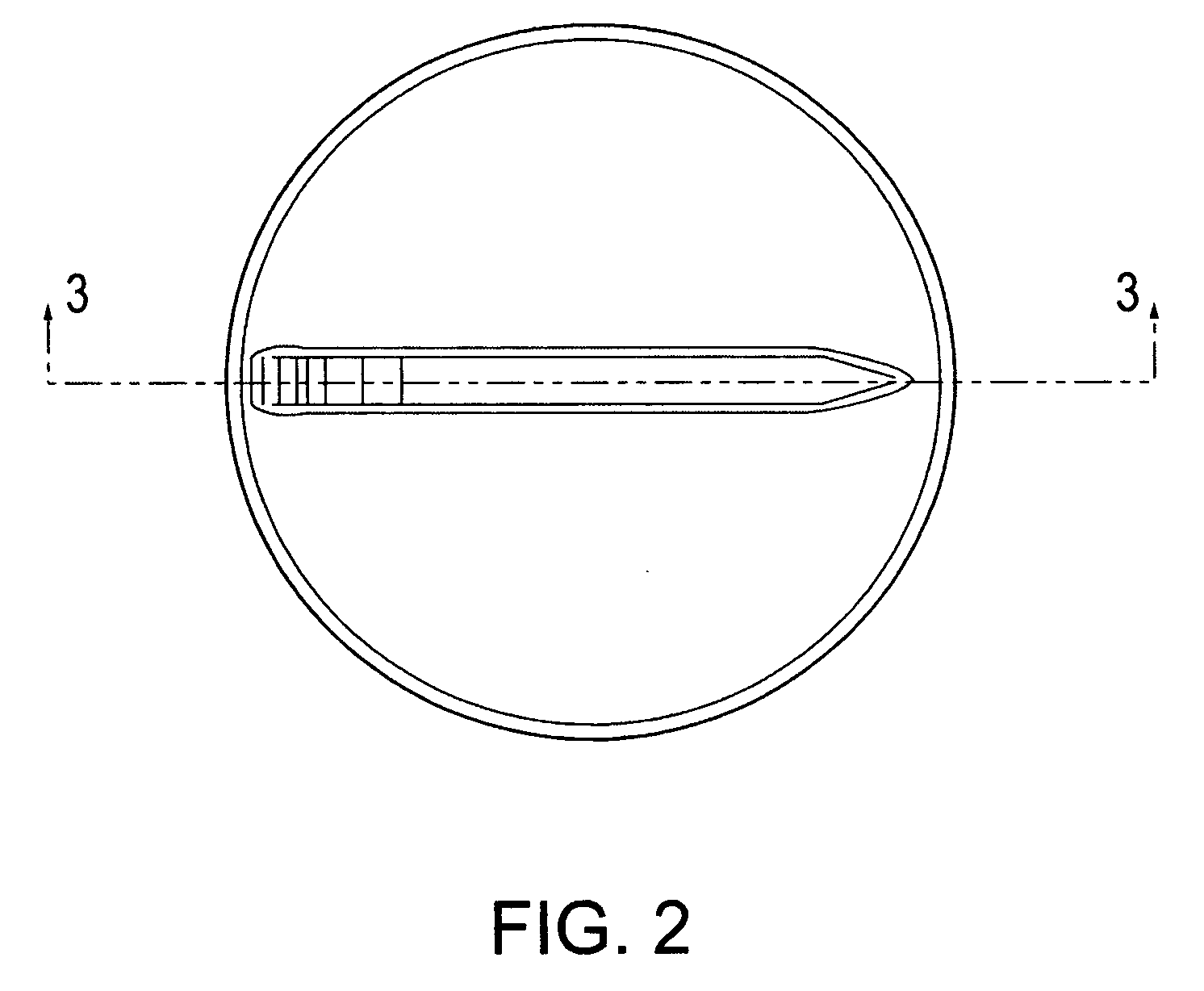
[0032] Referring first to FIGS. 1-3, a first embodiment of a flush cap assembly in accordance with the present invention, generally denoted at 10, comprises a body 12 and a cap 14 fitted over the top portion of body 12, and rotatably mounted thereon, as described more fully below. Cap 14 includes a top plate 18, a handle 16 extending upwardly from top plate 18, a sleeve 20 downwardly depending from top plate 18, and a circumferentially extending opening 22 in sleeve 20.

[0033] As best seen in FIGS. 1C and 3, body 12 includes a bottom portion 24 which is internally threaded at 25 for securing the flush cap assembly onto a spray head. If desired, the exterior surface of bottom portion 24 may be provided with a textured gripping surface, as by vertical ribs 36 (see FIGS. 1A, 1B, and 4) to facilitate installation and removal of the assembly 10 from the spray head.

[0034] Body 12 also includes an upper portion 27 having a circumferentially extending opening 26 adapted to be aligned with ...


PUM


Abstract

A flush cap assembly for a sprinkler head in an irrigation system comprising an array of sprinkler heads, the flush cap having a body portion adapted to be removably attached to a sprinkler head, an opening in the body portion communicating with a fluid flow path in the sprinkler head through which water can exit the sprinkler head during flushing of the irrigation system, and a cover portion which is manually movable to cover and uncover the opening in the body portion to selectively prevent water from exiting a particular sprinkler head during flushing of the irrigation system. Also disclosed is a method of preparing an irrigation system for use in which flush cap assemblies as described are employed. The cover portion may be rotatable or otherwise operable, and may include an opening which is alignable with the body opening to permit water to exit during flushing.

Description

CROSS-REFERENCE TO RELATED APPLICATIONS [0001] This application is based on and claims priority to U.S. Provisional Application 60 / 568,316, filed May 6, 2004, the entire disclosure of which is incorporated herein by reference.BACKGROUND OF THE INVENTION [0002] 1. Technical Field of the Invention [0003] This invention relates generally to underground irrigation systems that include a plurality of pop-up-type sprinklers connected to an irrigation source pipeline, and more particularly, to shipping or flush caps for such sprinklers. [0004] 2. Related Art [0005] Manufacturers of turf irrigation systems often supply the sprinklers with flush caps to cover the opening of the spray heads instead of a nozzle which will be used for normal operation. During installation, a shallow trench is dug in the desired layout, and the network of irrigation supply piping is laid out in the trench. The spray heads are then attached to the piping with the caps still attached, the water supply is connected...

Claims


Application Information

Patent Timeline
IPC IPC(8): B05B15/02
CPCB05B15/02B05B15/50
Inventor ZHANG, RICHARD
Owner K RAIN MFG
Why Eureka
Try Eureka