Rotorcraft blade provided with a tiltable flap and a fastener tongue

a technology of fastener tongue and rotorcraft blade, which is applied in the direction of propellers, propulsive elements, water-acting propulsive elements, etc., can solve the problems of unusable and dangerous, noise or vibration disturbance, and premature wear

Inactive Publication Date: 2009-09-29
EUROCOPTER
View PDF4 Cites 10 Cited by
  • Summary
  • Abstract
  • Description
  • Claims
  • Application Information

AI Technical Summary

Benefits of technology

[0016]Furthermore, as mentioned above, it is important for the assembly to be robust in order to avoid premature wear or even jamming of the flap, which might be catastrophic.
[0017]Finally, in order to reduce the inertial forces exerted on the blade and the flap, it is essential for the weight of the assembly to remain as small as possible.
[0021]The use of such a fastener ball joint makes it possible to satisfy the problem given the reputation for robustness of such mechanical equipment. In addition, there is no longer any need to provide the flap with a longitudinal shaft or with stub axles in order to allow it to pivot, thereby limiting any risk of the flap jamming.
[0022]Advantageously, the blade has a suction side face and a pressure side face, which faces meet at a trailing edge of the blade in order to form the tongue, in particular so as to obtain a tongue that is rigid. The stiffness of the tongue makes it possible to avoid any significant loss of effectiveness of the flap by preventing a return moment that would otherwise be induced by a flexible tongue.
[0027]Furthermore, the tongue is of great importance for aerodynamic and acoustic reasons. It avoids any discontinuity between the flap and the blade, thus preventing air from flowing between them. This advantage is maximized when the tongue extends along the entire span of the flap, i.e. when the tongue is at least as long as the flap. Nevertheless, given the presence of at least one control arm, the tongue comprises at least two distinct portions disposed on either side of a control arm.

Problems solved by technology

Nevertheless, under the effect of the stresses exerted on the blade and on the flap in flight, in particular those caused by beating movements, there is a risk of the flap sliding along the bearing point which could lead to premature wear, or even, in a worse-case scenario, to the flap becoming jammed, thereby making it unusable and dangerous.
Furthermore, it can readily be seen that the overall shape of the flap, and more particularly of its leading edge, is not optimized from an aerodynamic point of view and that might possibly lead to noise or vibration disturbance and to degraded aerodynamic performance.
The connecting rod is thus situated in part outside the blade-and-flap assembly, which is harmful to overall aerodynamics.
In addition, discontinuity is observed between the flap and the blade which can lead to a reduction in aerodynamic performance and also to a whistling effect due to air flowing between the flap and the blade.
In this second type of architecture, the means enabling the flap to pivot about a shaft still present the drawback of it being possible for the flap to jam.
Consequently, there is a non-negligible risk of the shaft being deformed, and under such circumstances the flap could then no longer be tilted to the desired angle of inclination.
Nevertheless, as for the second type of blade, the stub axles about which the flap tilts do not appear to present sufficient overall robustness to guarantee proper operation of the system over a reasonable length of time.

Method used


Image

  • Rotorcraft blade provided with a tiltable flap and a fastener tongue
  • Rotorcraft blade provided with a tiltable flap and a fastener tongue
  • Rotorcraft blade provided with a tiltable flap and a fastener tongue

Examples


first embodiment

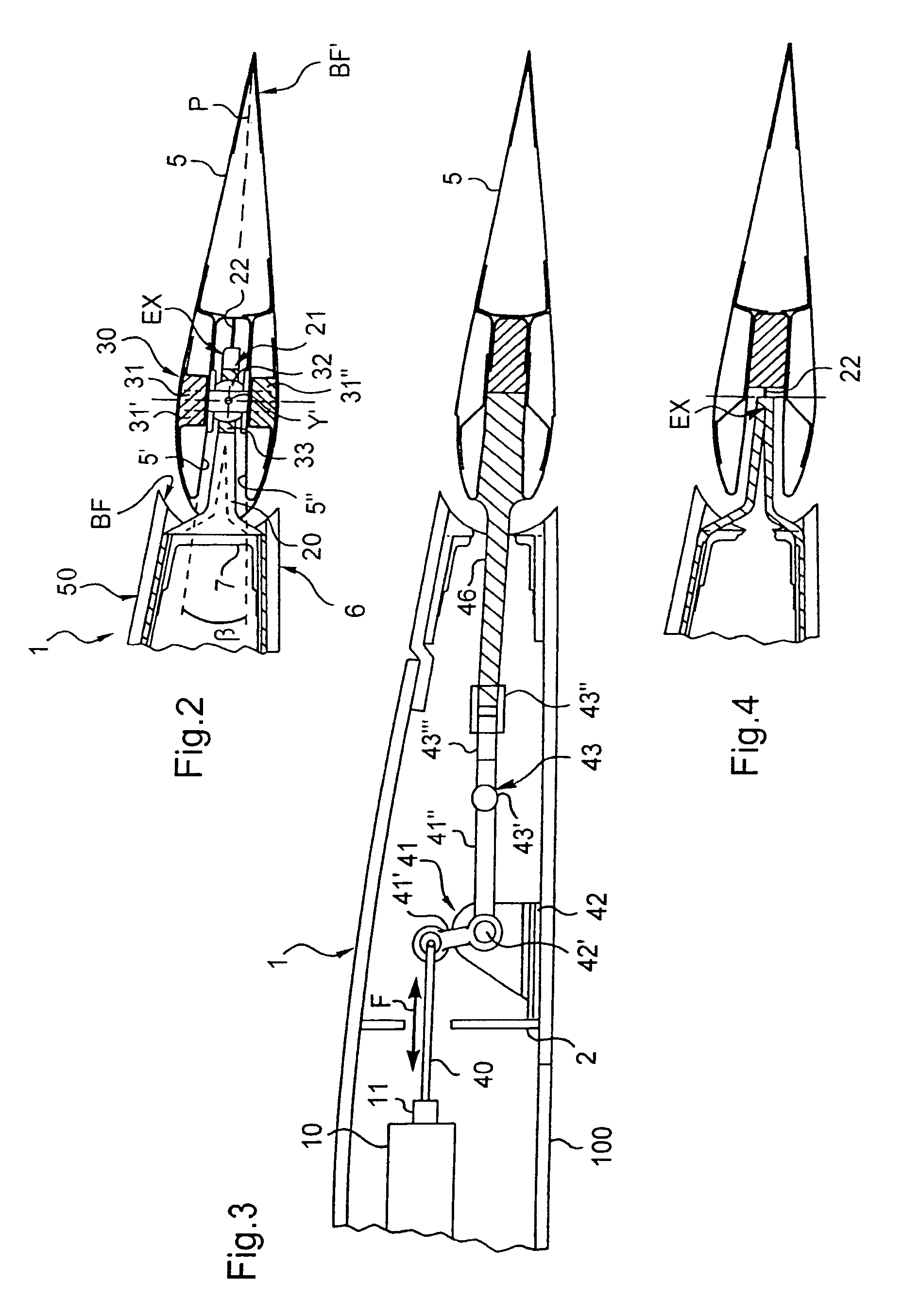
[0055]FIG. 3 is a section of FIG. 1 showing a zone of the flap 5 that is provided with the control arm.

[0056]Whatever the embodiment, the control arm 46 is secured to the flap 5, e.g. by being embedded therein at the time of manufacture. Titling the control arm 46 thus causes the flap 5 to tilt in the same manner.

[0057]In the first embodiment, the actuator 10 is of the linear type, having an end 11 suitable for moving along an axis X as represented by double-headed arrow F. It should be observed that an access hatch 100 is provided in the pressure side face of the blade 1 to enable maintenance operations to be performed on the actuator 10, for example.

[0058]The transmission linkage serving to connect the actuator 10 to the flap 5 comprises in succession: a first connecting rod 40; a bended crank 41; an extensible flexible pivot 43; and the control arm 46.

[0059]The first connecting rod 40, which also passes through the rib 2, is secured firstly to the end 11 of the actuator, and seco...

second embodiment

[0064]In a second embodiment that is not shown in a figure, the actuator is of the rotary type. A device, e.g. a device of the type described above, that allows for lengthening along the axis X is then disposed between the control arm 46 and the rotary actuator.

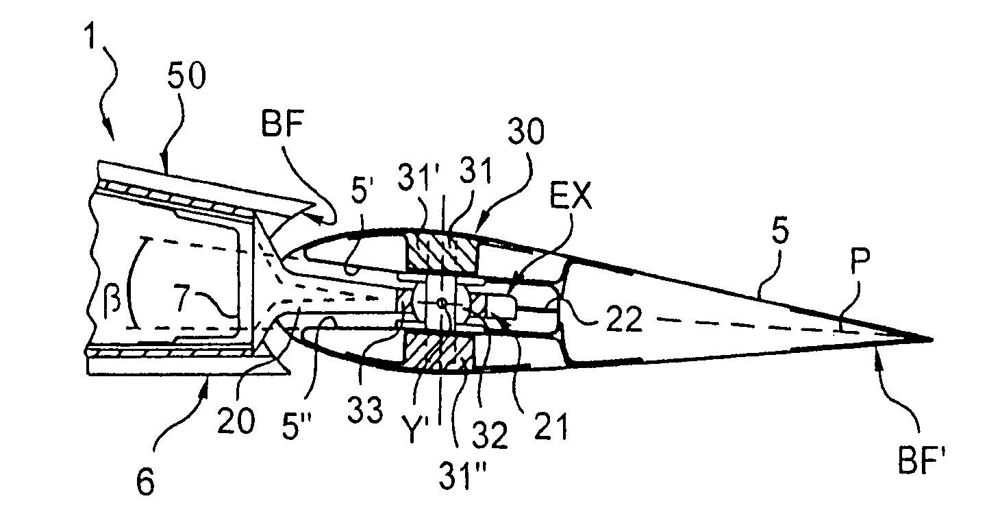
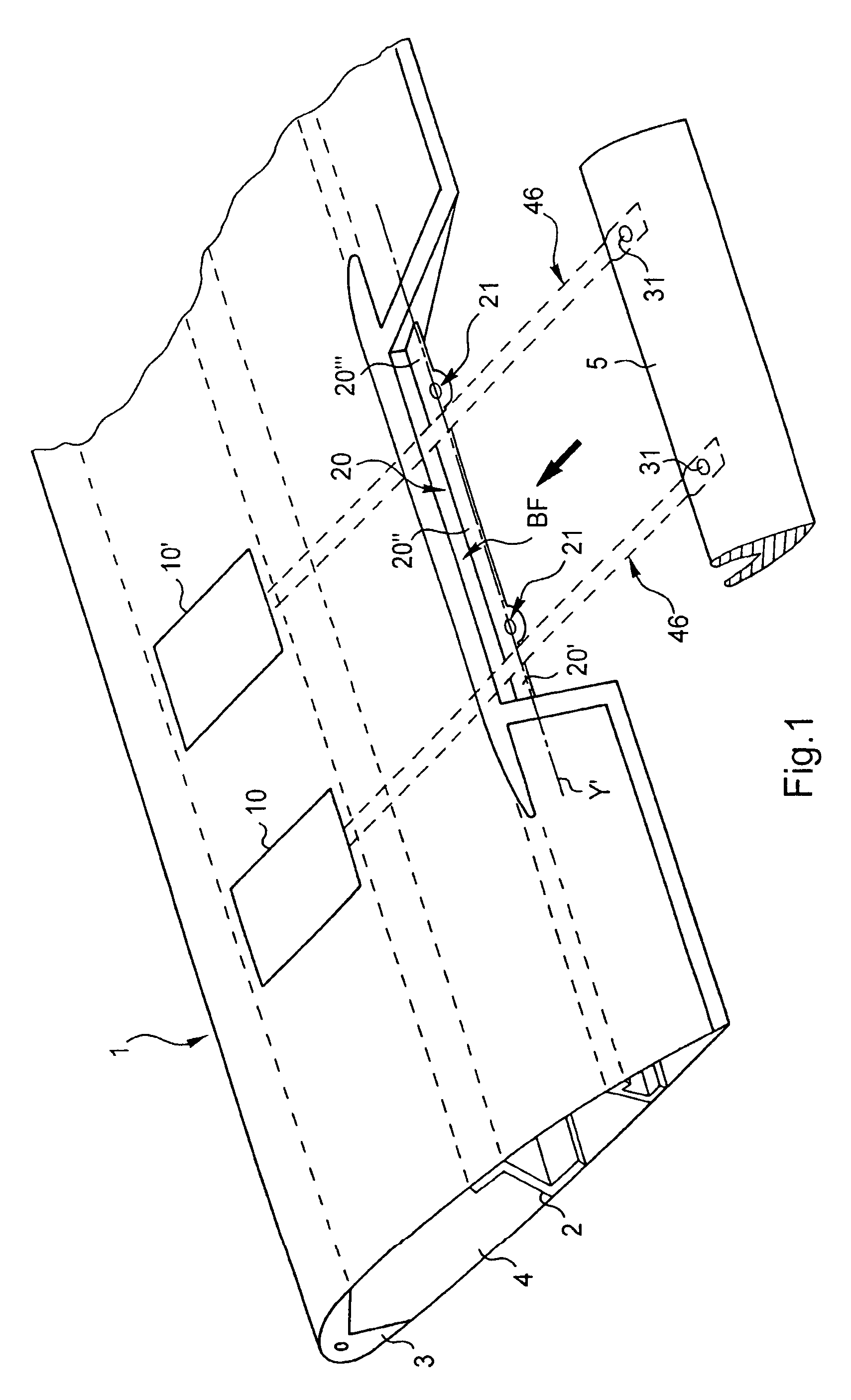
[0065]FIG. 4 is a section of FIG. 1 in a zone of the flap 5 that has neither a fastener ball joint 30 nor a control arm 46.

[0066]It can then be seen that the free end EX of the tongue 20 is provided with a flexible tape 22, as explained above for the zone shown in FIG. 2.


PUM


Abstract

The present invention relates to a rotorcraft rotor blade (1) that comprises at least one tiltable trailing-edge flap (5), said flap (5) being suitable for pivoting about a virtual hinge axis (Y′) extending substantially in the span direction of said blade (1) and of said flap (5). The blade (1) is remarkable in that the flap (5) is provided with at least two fastener ball joints (30), each provided with an inner cage (32) together with an outer cage (33) and a first pin (31) that is also secured to said flap (5), the first pins (31) of the fastener ball joints (30) being perpendicular to the virtual pivot axis (Y′) of the flap (5). In addition, the blade (1) is provided at its trailing edge (BF) with a fastener tongue (20) provided with ball-receiving sockets (21), the outer cages (33) of the fastener ball joints (30) being secured to the ball-receiving sockets (21).

Description

[0001]The present invention relates to an active blade for a rotorcraft, the blade being provided at its trailing edge with a fastener tongue and with a tiltable flap that is controlled locally by an electromechanical device.BACKGROUND OF THE INVENTION[0002]In order to improve the aero-acoustic, vibratory, and aerodynamic performance of the blades of a main lift and advance rotor of a rotorcraft, it is advantageous to place a tiltable flap in the trailing edge of each blade, which flap is conveniently referred to as a trailing edge flap.[0003]The angle through which the flap can be tilted relative to the blade is of the order of ±10° at a frequency of about 30 hertz (Hz). To be effective, the angle of tilt varies actively over time as a function of numerous parameters such as the position of the blade about the axis of the main rotor, referred to as the “azimuth” position, the speed of rotation of the main rotor, and the pitch, beating, and lag movements of the blade.[0004]Given the...

Claims


Application Information

Patent Timeline
Patent Type & Authority Patents(United States)
IPC IPC(8): B64C9/00
CPCB64C27/615B64C27/72B64C2027/7272Y02T50/34Y02T50/30
Inventor DE LA GRANDMAISON, FRANCOIS LORINMORANT, MICHELGAFFIERO, JACQUES
Owner EUROCOPTER
Why Eureka
Try Eureka