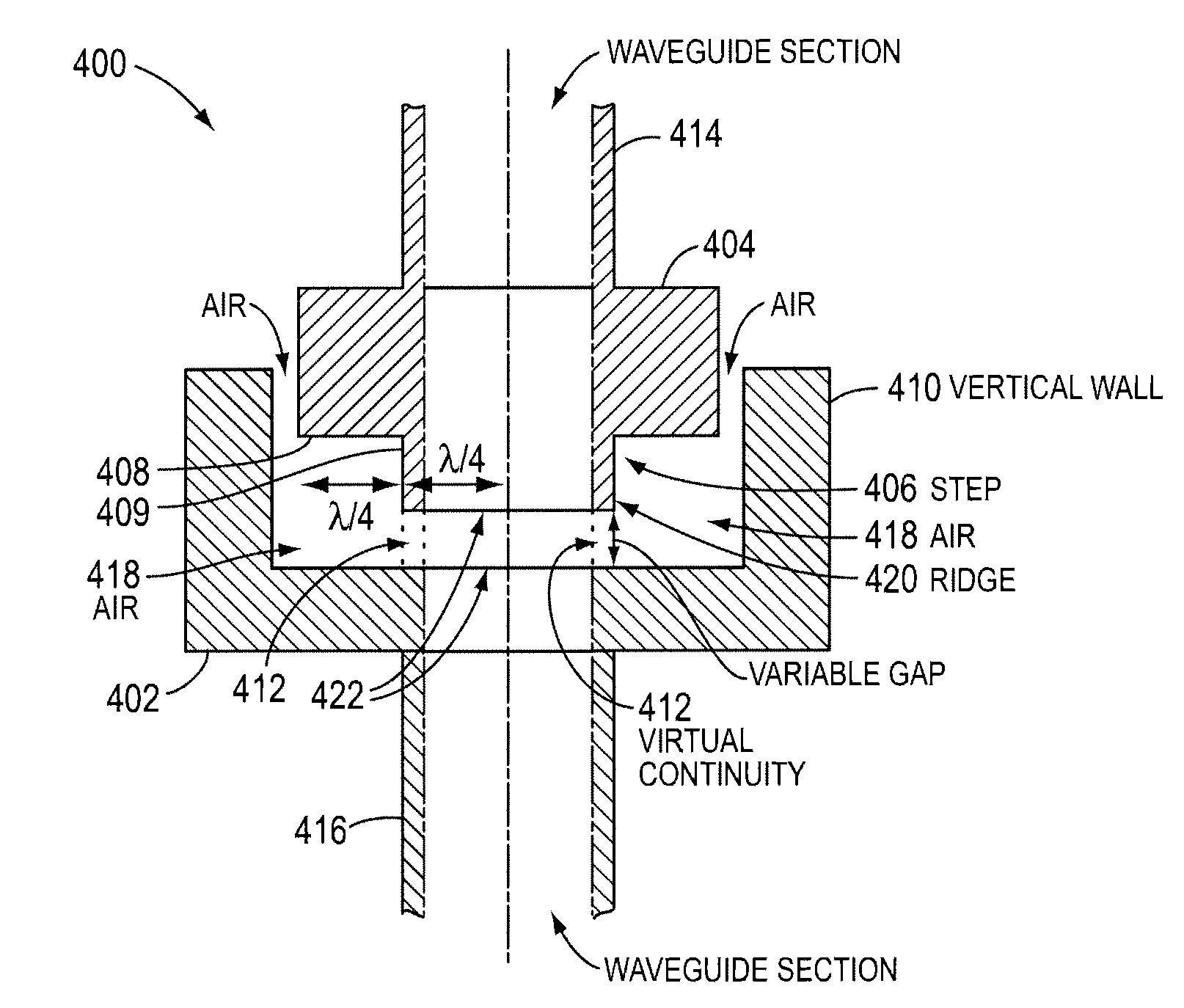
Waveguide interface having a choke flange facing a shielding flange
- Summary
- Abstract
- Description
- Claims
- Application Information
AI Technical Summary
Benefits of technology
Problems solved by technology
Method used
Image
Examples
Embodiment Construction
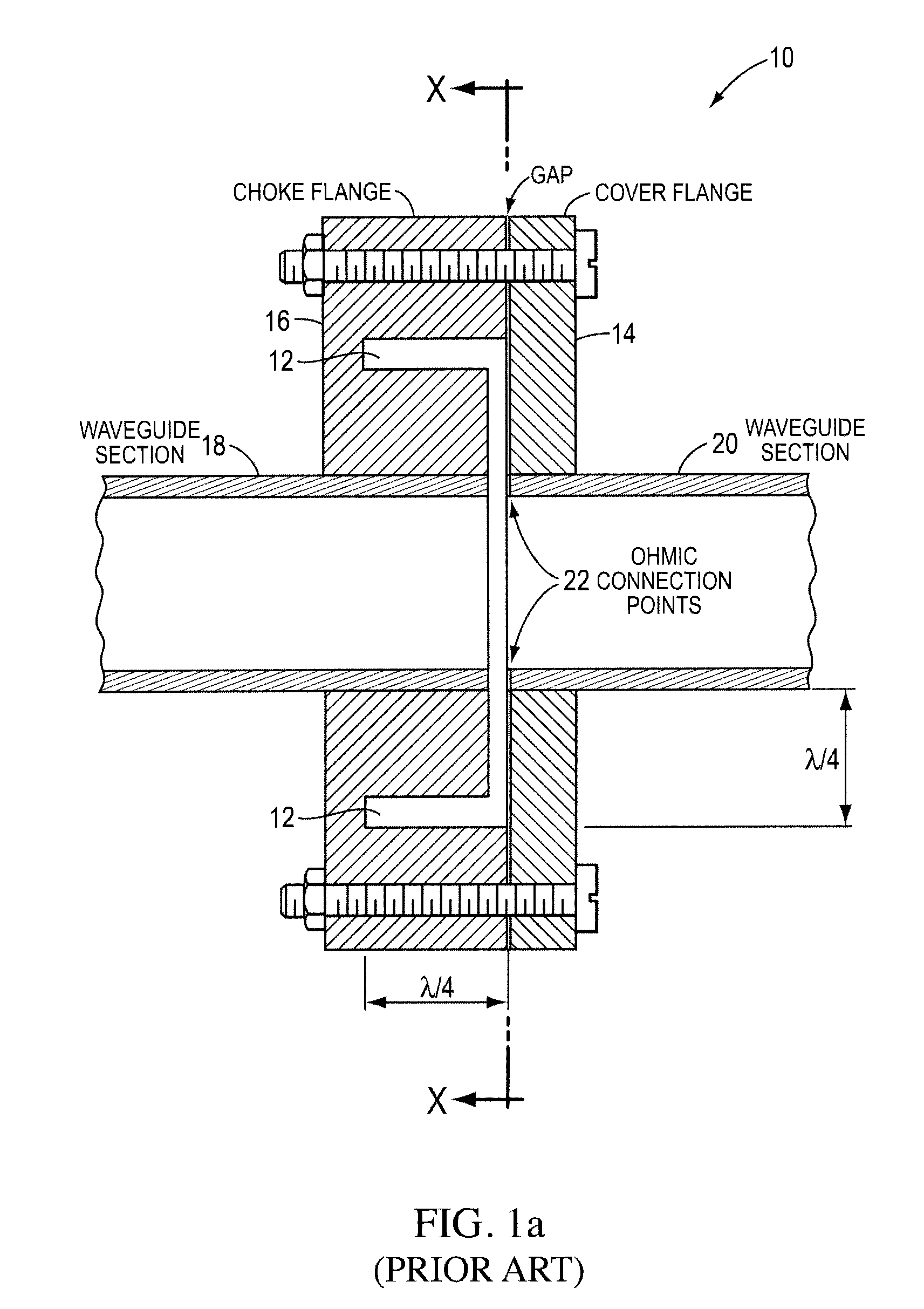
[0022]As noted above, the present invention relates to waveguide interfaces. The design of waveguide interfaces in accordance with the present invention is based, in part, on the observation that, with proper geometry, a half-wave groove at the connection point between two waveguides appears to the passing waves as a virtual continuity through the joint in the transmission line.
[0023]FIG. 4a illustrates the foregoing principle. The transmission line is interrupted with a groove 302 having a half-wavelength dimension (λ / 2). The groove is analogous to a tank circuit with inductance, L, and capacitance, C. The resonance frequency, fc, of the analogous tank circuit is derived from the equation:
[0024]fc=12πLC.1.
The resonance frequency, fc, is the center frequency in the frequency band. The graph of FIG. 4b shows the resonance frequency of the tank circuit within the frequency band, between f1 and f2. The in-band resonance or center frequency is the frequency for which the groove would...
PUM
 Abstract
Description
Claims
Application Information
 - R&D Engineer
- R&D Manager
- IP Professional
- Industry Leading Data Capabilities
- Powerful AI technology
- Patent DNA Extraction
Browse by: Latest US Patents, China's latest patents, Technical Efficacy Thesaurus, Application Domain, Technology Topic, Popular Technical Reports.
© 2024 PatSnap. All rights reserved.Legal|Privacy policy|Modern Slavery Act Transparency Statement|Sitemap|About US| Contact US: help@patsnap.com


