
Switching an electrical voltage source converter

a technology of electrical voltage and converter, which is applied in the direction of power conversion systems, control systems, ac-ac conversion, etc., can solve the problems of machinery oscillation, pronounced resonance frequency, and increase in machinery wear or equipment failure, so as to facilitate the reduction of higher order harmonics and low speed

Active Publication Date: 2019-09-05
ABB (SCHWEIZ) AG
View PDF3 Cites 1 Cited by
  • Summary
  • Abstract
  • Description
  • Claims
  • Application Information

AI Technical Summary

Benefits of technology

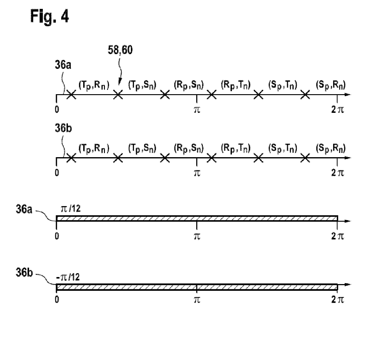
[0038]According to an embodiment of the invention, the pulse number is non-integer. For example, when the pulse number is a multiple of (2n+1)/2 with n=1, 2, 3, . . . ,

Problems solved by technology

These drive trains often possess some pronounced resonance frequencies, which, if excited, can result in high torsional oscillations resulting in increased wear of the machinery or a failure of equipment.
In typical drive train installations, the drive shaft is comparably long and thin, resulting in pronounced resonance frequencies at which, if excited, the masses of the rotor of the synchronous machine and the machinery oscillate against each other.
While the inertias and the elasticity of the elements of the drive shaft can be determined from their design and material characteristics an

Method used


Image

  • Switching an electrical voltage source converter
  • Switching an electrical voltage source converter
  • Switching an electrical voltage source converter

Examples


Embodiment Construction

[0012]In the pulse mode, higher harmonics may be produced, which may get into resonance with the torsional natural frequencies (TNFs) of the drive shaft.

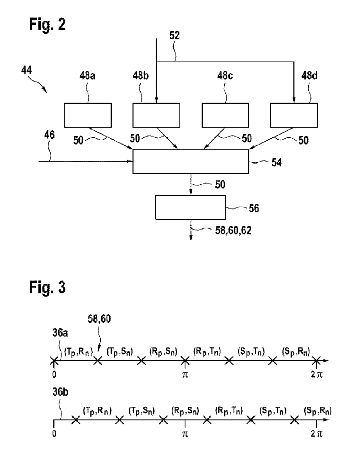
[0013]It is an objective of the invention to operate a thyristor-based inverter during pulse mode, such that an excitation of natural frequencies of the drive shaft stays low.

[0014]This objective is achieved by the subject-matter of the independent claims. Further exemplary embodiments are evident from the dependent claims and the following description.

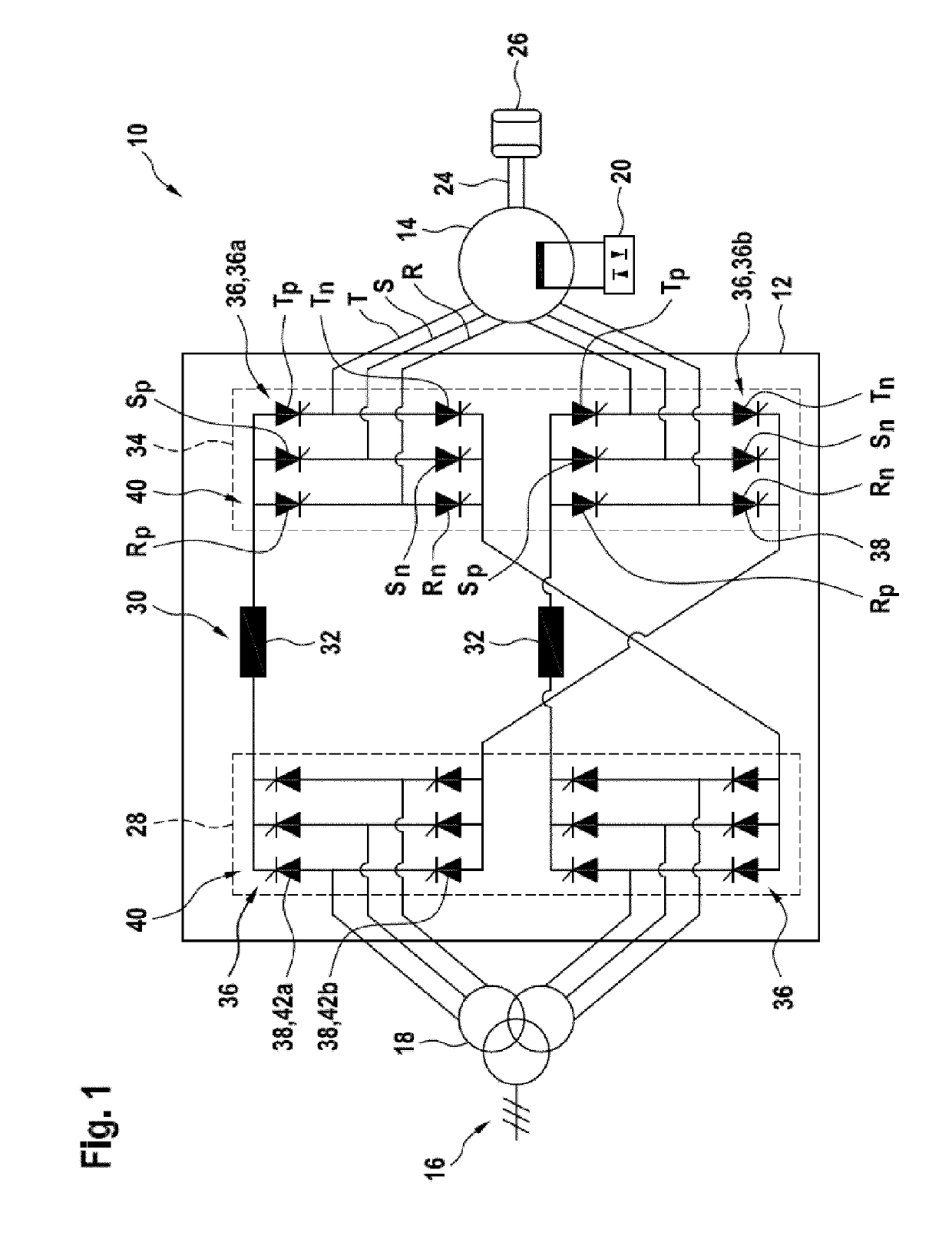
[0015]A first aspect of the invention relates to a method for switching an electrical converter with at least two output phases. The electrical converter may be a power converter adapted for converting currents of more than 10 A and / or more than 1 kV. The electrical converter may comprise a rectifier and a thyristor-based inverter, which are interconnected by a DC link with an inductor. In other words, the converter may be a current source converter. The thyristor-based inverter may b...


PUM


Abstract

An electrical converter with at least two output phases includes a rectifier and a thyristor-based inverter interconnected by a DC link with an inductor, wherein the thyristor-based inverter includes a half-bridge with at least two half-bridge arms for each output phase of the electrical converter and each arm being provided by a thyristor. A method for switching the electrical converter includes: cyclically switching the thyristors of the inverter, such that at least one time instant, two thyristors of different half-bridge arms are switched on simultaneously, such that a pulse number, which determines at how many time instants thyristors of the inverter are switched during one stator voltage period, is lower than the number of half-bridge arms of the inverter.

Description

FIELD OF THE INVENTION[0001]The invention relates to the field of current source inverters. In particular, the invention relates to a method for switching an electrical converter, a controller and an electrical drive system.BACKGROUND OF THE INVENTION[0002]A variable speed synchronous machine may be connected to an electrical grid via a line commutated rectifier and a load commutated inverter. This type of variable speed solution is often the preferred choice in high power applications, ranging from a few megawatts to over a hundred megawatts. For example, such applications include high speed compressors and rolling mills.[0003]Electric drives such as the load commutated inverter are typically employed to transform AC power of fixed frequency into AC power of varying frequency, or vice versa. The AC power of fixed frequency is provided by the electric grid, while the AC power of varying frequency is used to drive an electric AC machine such as the synchronous machine. By means of el...

Claims


Application Information

Patent Timeline
IPC IPC(8): H02M7/525H02M5/451H02P27/06H02P25/024
CPCH02M7/525H02P25/024H02P27/06H02M5/451
Inventor BESSELMANN, THOMASBRUHA, MARTINPIEDER, JOERGALMER, STEFAN
Owner ABB (SCHWEIZ) AG
Learn More