
Class-D line driver arrangement

a technology of line driver and driver, applied in the direction of amplifiers, amplifiers with semiconductor devices/discharge tubes, electrical devices, etc., can solve the problems of insufficient heat dissipation, inconvenient use, and inability to provide low-pass filters which remove high-frequency carriers or switching frequency fs, etc., to achieve low cost, low resonance, and simple construction on circuit boards

Inactive Publication Date: 2005-07-21
INFINEON TECH AG
View PDF7 Cites 0 Cited by
  • Summary
  • Abstract
  • Description
  • Claims
  • Application Information

AI Technical Summary

Benefits of technology

The invention provides a line driver arrangement that uses a class-D amplifier and a transformer for low-pass filtering of the amplified transmit signal. This arrangement is smaller and cost-efficient compared to traditional line driver arrangements that use discrete inductors or capacitances. The leakage inductance of the transformer is predetermined to minimize resonance at a resonance frequency in the power spectral density of the line driver arrangement. The arrangement also includes a capacitance connected between the two lines carrying the dual line signal, which forms a low-pass filter with a cutoff frequency that is lower than the resonance frequency. The invention also provides a transformer with a predetermined leakage inductance or stray capacitance to further improve the filter properties and compliance with stricter PSD mask requirements.

Problems solved by technology

However, driving transistors in a class-AB amplifier are biased to operate in their linear region which results in that they are always in an on-state and draw precious quiescent current.
This results in an inefficient power dissipation.
However, a drawback of class-D amplifiers is that a low-pass filter which removes the high-frequency carrier or switching frequency FS must be provided.
It is a disadvantage that the inductances L1 and L2 must be placed on a circuit board carrying the line driver arrangement.
This may lead to additional heat dissipation, the inductances require additional assembling steps and considerable amount of space.
Thus, additional costs are created by the use of discrete inductances on a circuit board for a line driver arrangement comprising a class-D power amplifier over the gain in power efficiency.

Method used


Image

  • Class-D line driver arrangement
  • Class-D line driver arrangement
  • Class-D line driver arrangement

Examples


Embodiment Construction

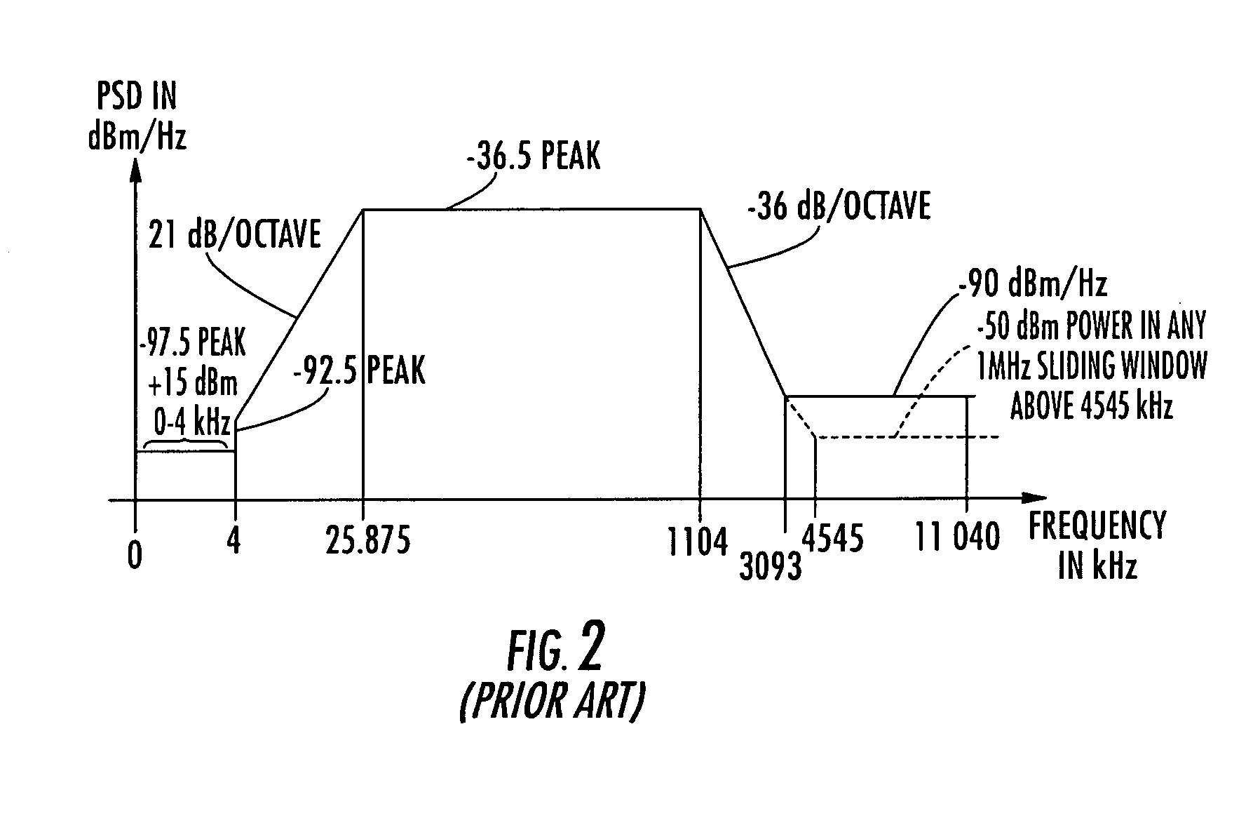
[0041]FIG. 1-4 are already depicted in the introduction of the specification.

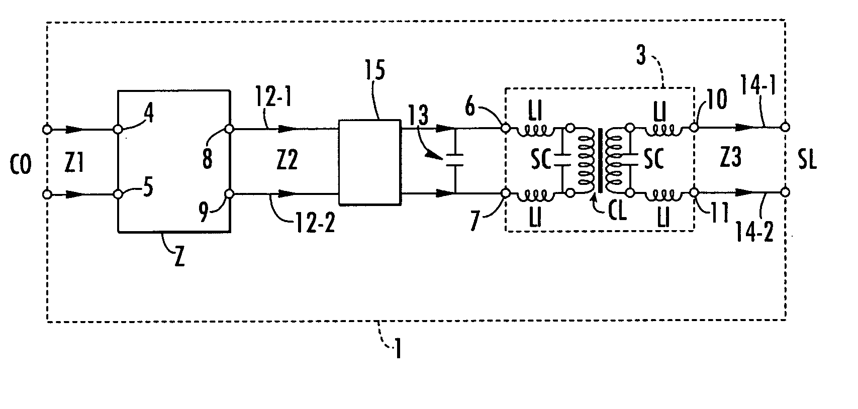
[0042]FIG. 5 shows a block diagram of the inventive line driver arrangement.

[0043] The inventive line driver arrangement 1 comprises a class-D switching amplifier 2 having two input terminals 4, 5 and two output terminals 8, 9. The class-D amplifier 2 has a switching frequency FS and receives an input transmit signal Z1 in / from a central office CO and outputs an amplified transmit signal Z2 to a dual line 12-1, 12-2. The line driver arrangement further comprises a transformer 3 that has a predetermined leakage inductance for receiving the amplified transmit signal Z2 on its two inputs 6, 7. The transformer couples the amplified transmit signal Z2 to the dual telephone line 14-1, 14-2. The transformer receives the amplifier transmit signal Z2 on its input terminals 6, 7 and outputs the output transmit signal Z3 on its output terminals 10, 11 to a subscriber line SL. A leakage inductance of the transformer ...


PUM


Abstract

Line driver arrangement comprising a class-D switching amplifier having a switching frequency for receiving an input transmit signal and outputting an amplified transmit signal and a transformer having a predetermined leakage inductance for receiving the amplified transmit signal and outputting a transform signal as an output transmit signal. The leakage inductance is predetermined for low-pass filtering of the amplified transmit signal. The line driver arrangement reduces the number of additional discrete inductances, capacitances and or resistor for forming low-pass filters significantly. The inventive line driver arrangement is particularly power-efficient due to the included class-D switching amplifier. The predetermined leakage inductance leads to a suppression of a resonance due to the switching frequency of the class-D amplifier in the power spectral density. Hence, the inventive line driver arrangement complies at least with the ADSL PSD mask requirements.

Description

BACKGROUND OF THE INVENTION [0001] The invention relates to a line driver arrangement utilizing class-D power amplifiers, in particular for a DSL line driver, and a transformer for use therein. [0002] Digital subscriber lines (DSL) provide the key technologies in our days and help to improve the speed of communications networks. DSL offers extremely fast data transfer on existing copper-based telephone lines. In DSL, broad-band data signals are transmitted on significantly higher frequencies than the traditional narrow-band telephone signals. Since both types of signals, the narrow-band telephone signals and the broad-band data signals, are transmitted over the same subscriber line, splitter devices are provided for splitting and recombining the two types of signals at both ends of the subscriber line: first at the central office or switching center, and second at the end terminals at the subscriber location. [0003]FIG. 1 shows schematically the topology of such an audio telephone n...

Claims


Application Information

Patent Timeline
Patent Type & Authority Applications(United States)
IPC IPC(8): H03F3/217H04M1/738H04M11/06H04Q1/54
CPCH03F3/217
Inventor RANDAHL, TORBJORNJOHANSSON, CARL-MIKAELBARKARO, STEFANBOKINGE, BOKARLSSON, LARS
Owner INFINEON TECH AG
Learn More