
Method and apparatus for currency discrimination

a currency and discrimination technology, applied in the field of currency identification, can solve the problems of requiring a correspondingly longer period of time to process data, slowing down the rate at which incoming bills may be scanned, and requiring a correspondingly large amount of time, so as to achieve efficient discrimination among bills, high degree of accuracy, and high speed

Inactive Publication Date: 2009-09-15
CUMMINS-ALLISON CORP
View PDF369 Cites 87 Cited by
  • Summary
  • Abstract
  • Description
  • Claims
  • Application Information

AI Technical Summary

Benefits of technology

The technique enables fast and accurate identification of multiple currency denominations by reducing the number of samples required, improving processing speed, and enhancing system efficiency while maintaining high accuracy.

Problems solved by technology

A major obstacle in implementing automated currency discrimination systems is obtaining an optimum compromise between the criteria used to adequately define the characteristic pattern for a particular currency denomination and the time required to analyze test data and compare it to predefined parameters in order to identify the currency bill under scrutiny.
Even with the use of microprocessors for processing the test data resulting from the scanning of a bill, a finite amount of time is required for acquiring samples and for the process of comparing the test data to stored parameters to identify the denomination of the bill.
Most of the optical scanning systems available today utilize complex algorithms for obtaining a large number of reflectance data samples as a currency bill is scanned by an optical scanhead and for subsequently comparing the data to corresponding stored parameters to identify the bill denomination.
The use of the large number of data samples slows down the rate at which incoming bills may be scanned and, more importantly, requires a correspondingly longer period of time to process the data in accordance with the discrimination algorithm.
The end result is that systems capable of accurate currency discrimination are costly and generally incapable of currency discrimination at high speeds with a high degree of accuracy.

Method used


Image

  • Method and apparatus for currency discrimination
  • Method and apparatus for currency discrimination
  • Method and apparatus for currency discrimination

Examples


Embodiment Construction

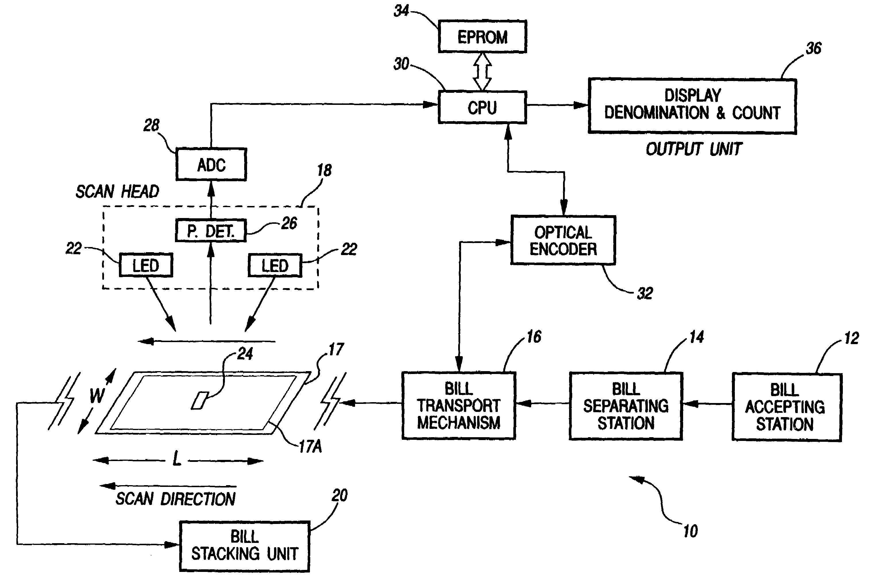
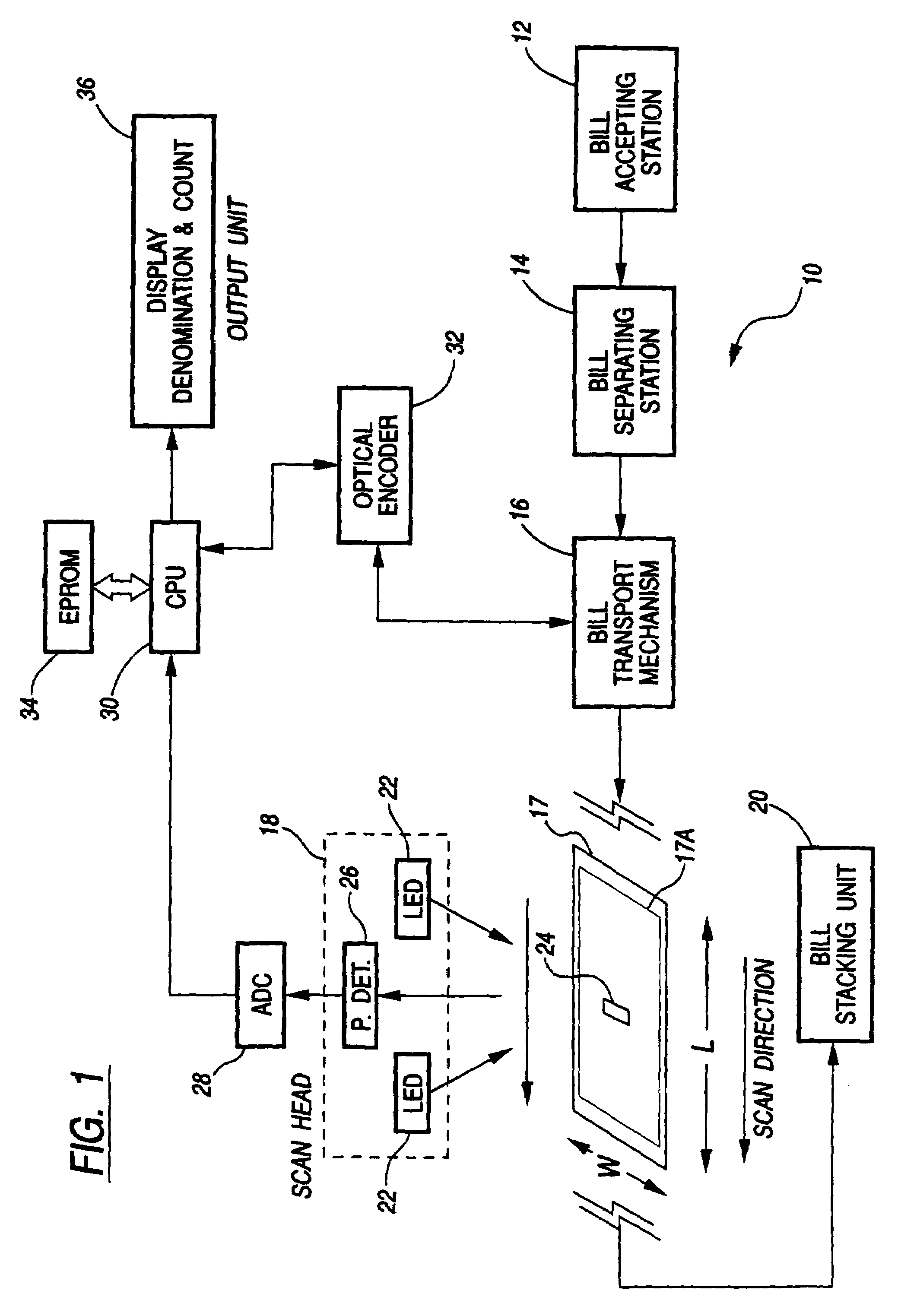
[0044]Referring now to FIG. 1, there is shown a functional block diagram illustrating the optical sensing and correlation system according to this invention. The system 10 includes a bill accepting station 12 where stacks of currency bills that need to be identified and counted are positioned. Accepted bills are acted upon by a bill separating station 14 which functions to pick out or separate one bill at a time for being sequentially relayed by a bill transport mechanism 16, according to a precisely predetermined transport path, across an optical scanhead 18 where the currency denomination of the bill is scanned, identified and counted at a rate in excess of 800 bills per minute. The scanned bill is then transported to a bill stacking station 20 where bills so processed are stacked for subsequent removal.

[0045]The optical scanhead 18 comprises at least one light source 22 directing a beam of coherent light downwardly onto the bill transport path so as to illuminate a substantially ...


PUM


Abstract

An improved method and apparatus for discriminating between currency bills of different denominations uses an optical sensing and correlation technique based on the sensing of bill reflectance characteristics obtained by illuminating and scanning a bill along one of its dimensions. A series of detected reflectance signals are obtained by sampling and digitally processing, under microprocessor control, the reflected light at a plurality of predefined sample points as a currency bill is moved across an illuminated strip with a preselected dimension parallel to the direction of transport of the bill. The sample data is subjected to digital processing, including a normalizing process, whereby the reflectance data represents a characteristic pattern that is unique for a given bill denomination and incorporates sufficient distinguishing features between characteristic patterns for discriminating between different currency denominations. A plurality of master characteristic patterns are generated and stored using original bills for each denomination of currency to be detected. The pattern generated by scanning a bill under test and processing the data samples is compared with each of the prestored master patterns to generate, for each comparison, a correlation number representing the extent of similarity between corresponding ones of the plurality of data samples for the compared patterns. Denomination identification is based on designating the scanned bill as belonging to the denomination corresponding to the stored master pattern for which the correlation number resulting from pattern comparison is determined to be the highest, subject to a bi-level threshold of correlation.

Description

CROSS-REFERENCE TO RELATED APPLICATIONS[0001]This application is a continuation of application Ser. No. 10 / 391,111, filed Mar. 18, 2003 now U.S. Pat. No. 7,248,731 and a continuation-in-part of application Ser. No. 10 / 163,757, filed Jun. 6, 2002; application Ser. No. 10 / 391,111 filed Mar. 18, 2003 is a continuation of application Ser. No. 08 / 226,660 filed Apr. 12, 1994, now issued as U.S. Pat. No. 6,539,104, which in turn is a continuation-in-part of application Ser. No. 08 / 127,334, filed Sep. 27, 1993, now issued as U.S. Pat. No. 5,467,405, which in turn is a continuation of application Ser. No. 07 / 885,648, filed May 19, 1992, now issued as U.S. Pat. No. 5,295,196; application Ser. No. 10 / 163,757 filed Jun. 6, 2002 is a continuation of application Ser. No. 09 / 453,200, filed Dec. 2, 1999, now issued as U.S. Pat. No. 6,459,806, which in turn is a continuation of application Ser. No. 08 / 841,203, filed Apr. 29, 1997, now issued as U.S. Pat. No. 6,028,951, which in turn is a continuatio...

Claims


Application Information

Patent Timeline
Patent Type & Authority Patents(United States)
IPC IPC(8): G06K9/00B65H3/06G06Q20/00G07D7/00G07D7/04G07D7/12G07D7/16G07D7/20G07D11/00G07F7/04G07F19/00
CPCB65H3/063G06Q20/18G07D7/12G07F19/20G07D7/122G07D7/162G07D7/20G07D7/205G07D11/0084G07F7/04G07D7/121B65H2301/541B65H2557/514B65H2701/1912G07D7/1205G07D11/50
Inventor RATERMAN, DONALD E.GRAVES, BRADFORD T.STROMME, LARS R.BAUCH, AARON M.
Owner CUMMINS-ALLISON CORP
Learn More