
Method and apparatus for gamma ray detection

a gamma ray and detection method technology, applied in the field of detection systems, can solve the problems of increasing sensitivity, reducing angular resolution somewhat, and not allowing the discrimination of scattered photon background, so as to achieve high spatial resolution, increase detector thickness, and high sensitivity

Inactive Publication Date: 2005-06-14
NOVA R&D
View PDF10 Cites 14 Cited by
  • Summary
  • Abstract
  • Description
  • Claims
  • Application Information

AI Technical Summary

Benefits of technology

[0014]The present invention provides a high sensitivity, high spatial resolution, and electronically collimated single photon emission computed tomography (SPECT) system. Its primary sensitivity is in the range of 81 keV to 511 keV although it can be used to detect higher energies of up to a few MeV by increasing the detector thickness for both the hodoscope and the calorimeter. Both the direction and energy of the incident gamma ray photons is measured with high resolution. The method of determination of the photon direction eliminates the need for a mechanical collimator and the energy measurement discriminates against the scattered photon background.
[0017]The scattered gamma ray photons can make a second Compton scatter and then escape without further interaction. Also the photons already scattered inside the patient will deposit lower total energy. These events will produce a tail at lower energies in the energy spectrum. Such events can be discriminated effectively because the total energy detected is smaller than the known incident gamma ray energy. However, a high sensitivity mode may be applied with reduced angular resolution by adding the missing energy to the energy measured at the second scatter. This will dramatically increase the sensitivity but reduce angular resolution somewhat and will not allow the discrimination of the scattered photon background.

Problems solved by technology

This will dramatically increase the sensitivity but reduce angular resolution somewhat and will not allow the discrimination of the scattered photon background.

Method used


Image

  • Method and apparatus for gamma ray detection
  • Method and apparatus for gamma ray detection
  • Method and apparatus for gamma ray detection

Examples


Embodiment Construction

Gamma Ray Detection

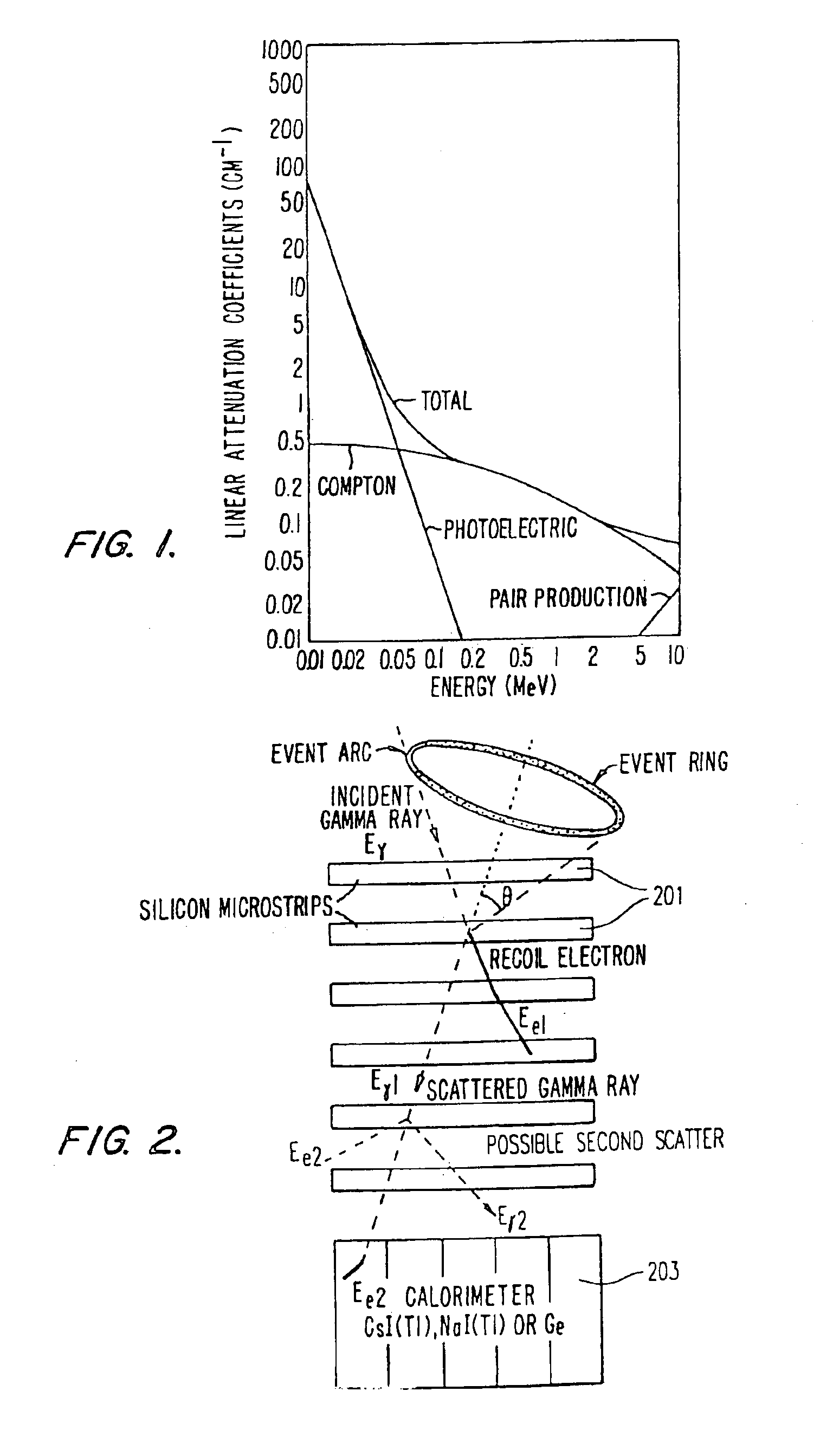
[0035]The most probable interaction mechanism for 0.05 to 10 MeV gamma rays in silicon is the Compton scatter process. Therefore, the detection of gamma rays in this energy range must use Compton interaction to have maximum sensitivity. The detector must also have excellent angular and energy resolution and a wide field-of-view. The best detection technique that has all of these features is the Compton double scatter method. This technique incorporates Compton scattering, photoelectric absorption, and pair production. The three gamma ray interaction mechanisms are briefly discussed below.

[0036]Although a number of possible interaction mechanisms are known for gamma rays in matter, only three major types play an important role in radiation detection: photoelectric absorption, Compton scattering, and pair production. Of these, only the first two play a major role in emission imaging. All of these processes lead to the partial or complete transfer of the photon energ...


PUM


Abstract

A high sensitivity, three-dimensional gamma ray detection and imaging system is provided. The system uses the Compton double scatter technique with recoil electron tracking. The system preferably includes two detector subassemblies; a silicon microstrip hodoscope and a calorimeter. In this system the incoming photon Compton scatters in the hodoscope. The second scatter layer is the calorimeter where the scattered gamma ray is totally absorbed. The recoil electron in the hodoscope is tracked through several detector planes until it stops. The x and y position signals from the first two planes of the electron track determine the direction of the recoil electron while the energy loss from all planes determines the energy of the recoil electron.

Description

CROSS-REFERENCES TO RELATED APPLICATIONS[0001]This application is a continuation of U.S. application Ser. No. 10 / 222,817 filed Aug. 19, 2002 now abandoned, which is a continuation of U.S. application Ser. No. 09 / 119,144 filed Jul. 20, 1998, now U S. Pat. No. 6,448,560, which is a continuation-in-part of U.S. application Ser. No. 08 / 784,176, filed Jan. 15, 1997 which is now U.S. Pat. No. 5,821,541 and which claims the benefit of U.S. Provisional Application Ser. No. 60 / 011,135, filed Feb. 2, 1996.GOVERNMENT RIGHTS NOTICE[0002]This invention was made with U.S. Government support under Contract Numbers R4MH49923 and DAMD17-96-1-6256 awarded by the Department of Health and Human Services and the Department of Defense, respectively. The U.S. Government as certain rights in the invention.FIELD OF THE INTENTION[0003]The present invention relates generally to detection systems, and more particularly, to a method and apparatus for imaging gamma rays.BACKGROUND OF THE INVENTION[0004]The vario...

Claims


Application Information

Patent Timeline
IPC IPC(8): G01T1/29G01T1/00
CPCG01T1/006A61B6/4258G01T1/2928G01T1/1647
Inventor TUMER, TUMAY O.
Owner NOVA R&D
Learn More