
Plasma arc power supply and control method for same

a technology of power supply and plasma arc, which is applied in the direction of dc-ac conversion without reversal, instruments, manufacturing tools, etc., can solve the problems of loss of energy p, poor efficiency, and unstable output load current, so as to reduce energy waste and reduce power consumption , the effect of distributing the risk of device-wide failur

Active Publication Date: 2009-09-08
SANSHA ELECTRIC MFG
View PDF6 Cites 4 Cited by
  • Summary
  • Abstract
  • Description
  • Claims
  • Application Information

AI Technical Summary

Benefits of technology

The present invention provides a plasma arc power supply with multiple direct-current power supply units that can efficiently handle small-current regions and increase load currents when needed. The invention also includes a relay circuit that ensures stable load current and reduces power consumption in small-current regions. Additionally, a soft start can be employed to prevent overshoot during startup of the power supply units. The invention also allows for a gradual startup of the power supply units to prevent damage to the surrounding environment. Furthermore, the invention reduces energy waste and increases stability in the small-current region.

Problems solved by technology

Such a loss in energy P creates poor efficiency in a small-current region in which only a low energy is originally needed.
Drawbacks therefore occur in that the outputted load current becomes more unstable, and the load current takes time to be stabilized.
When an extremely thin metal plate is welded or cut as the workpiece, or when only a small current is needed, such as when, for example, etching letters or symbols using the low current region on a workpiece, all of the direct-current power supply devices are used, and work therefore cannot be performed at a power savings, and energy is wasted.
The effect is small when a large current is fed, but the temperature of the torch rapidly increases when there is significant fluctuation in the current value in the small-current region, and there is a risk of electrode deformation or interruption of the arc.

Method used


Image

  • Plasma arc power supply and control method for same
  • Plasma arc power supply and control method for same
  • Plasma arc power supply and control method for same

Examples


embodiment 1

1. Embodiment 1

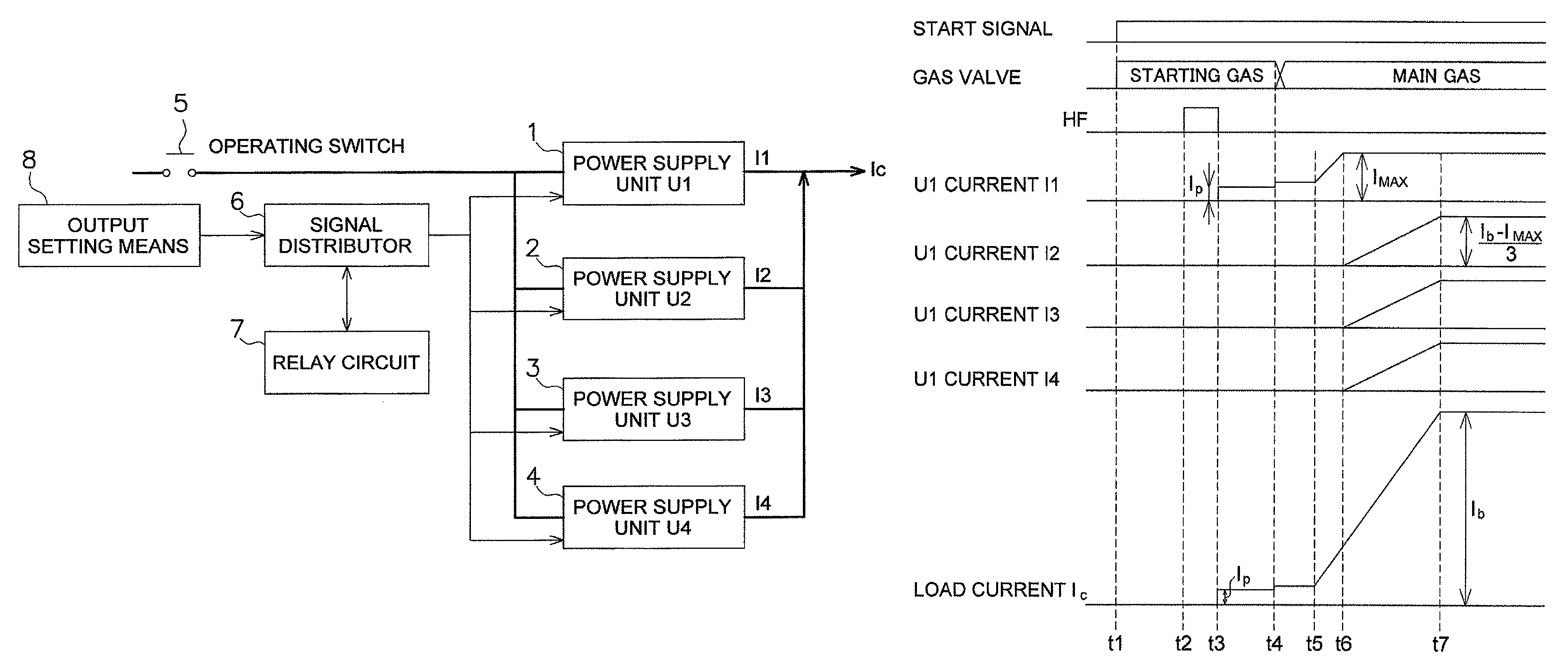
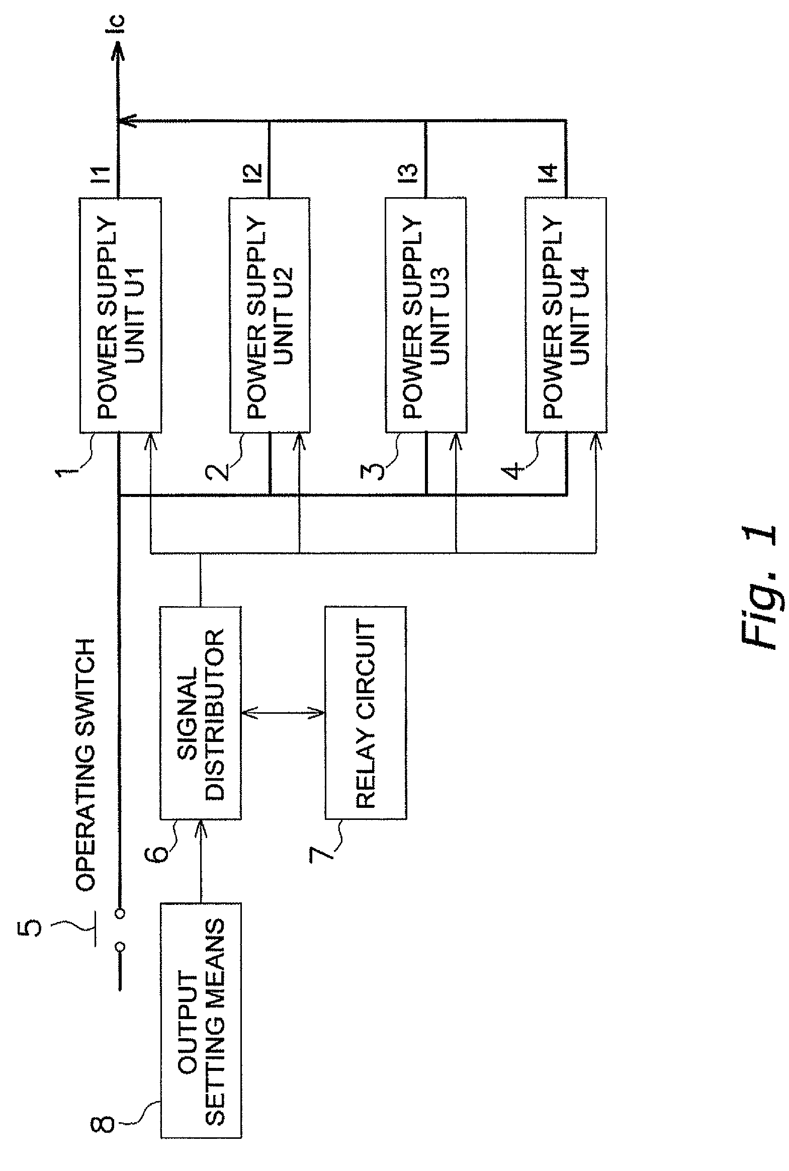
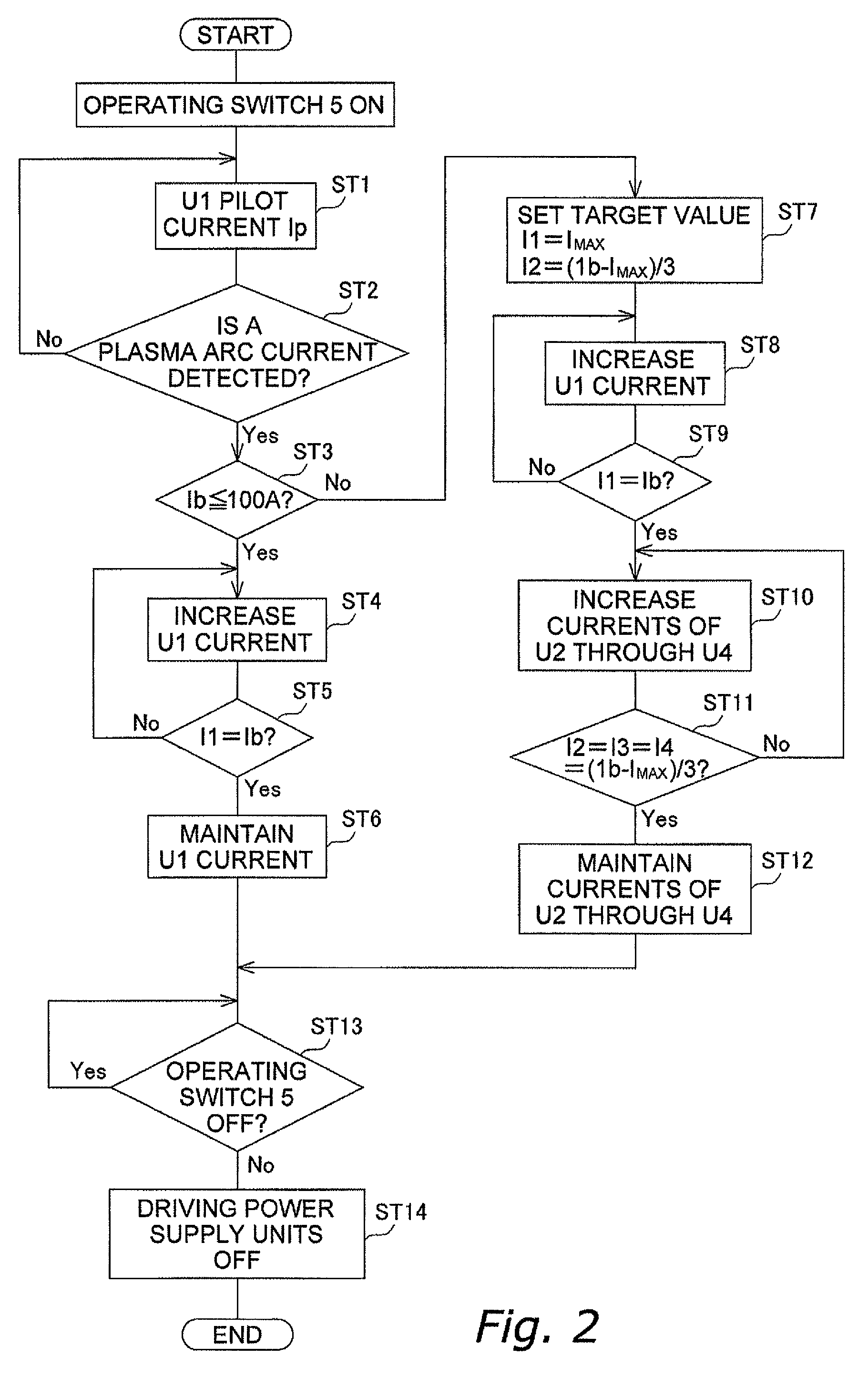
[0024]Embodiment 1 of the present invention will be described using FIGS. 1 through 3. FIG. 1 is a block diagram showing Embodiment 1 of the present invention; FIG. 2 is a flowchart relating to current; and FIG. 3 is a timing chart. The diagrams show a case in which N=4.

(1) Structure of Plasma Arc Power Supply

[0025]The plasma arc power supply shown in FIG. 1 is used in a welding machine or a cutting machine.

[0026]When an operating switch 5 is turned ON, power supply units U1 through U4 having the same structure are driven in a manner in which the startup timing is controlled by a relay circuit 7 and a signal distributor 6. The output currents I1 through I4 of the power supply units U1 through U4, respectively, are each feedback-controlled by a detection device not shown in the drawing, and are controlled so as to output a specified prescribed current. The current value of the load current Ic presented to the workpiece is specified by an output setting means 8, and can...

embodiment 2

2. Embodiment 2

[0043]An example was described in the aforementioned embodiment in which driving of the remaining power supply units U2 through U4 was initiated when the power supply unit U1 reached the rated current, but a configuration may also be adopted in which driving of the remaining power supply units U2 through U4 is initiated when the current from the power supply unit U1 reaches 80%, for example, of the rated current, as shown in FIG. 4. The load current Ib in this case is smaller than the load current Ib of the aforementioned embodiment.

[0044]Specifically, the target value of the current I1 of the power supply unit U1 is Ira (e.g., 80 A), which is lower than the rated current IMAX, and the target value Irb of the currents I2 through I4 of the power supply units U2 through U4 is (Ib−Ira) / 3. Through the relay signal from the relay circuit 7, the current of the power supply unit 1 begins to increase at t5 in the same manner described above after the current stabilizes, the p...


PUM

PropertyMeasurementUnit
currentaaaaaaaaaa
current regionaaaaaaaaaa
currentaaaaaaaaaa

Abstract

Energy loss due to driving a plurality of power supply units simultaneously in a low-current region is prevented, and a more stable load current is obtained. The generation of a load current in a small-current region from a pilot arc current is handled solely by the power supply unit U1, the remaining (N−1) power supply units U2 through U4 are driven when the small-current region is exceeded, and a current that is the composite of all the currents is fed to the load, whereby a stable plasma arc power supply is obtained in which power consumption in the low-current region is reduced.

Description

BACKGROUND OF THE INVENTION[0001]1. Field of the Invention[0002]The present invention relates to a plasma arc power supply of a welding machine or a cutting machine that uses a plurality of power supply units, and to a control method for the plasma arc power supply.[0003]2. Description of the Related Art[0004]An inverter plasma arc power supply is well known conventionally as a plasma arc power supply used in welding machines or cutting machines. The capacity of welding machines or cutting machines is adjusted from a small-current region to a large-current region for use according to the application.[0005]Japanese Laid-open Patent Application No. 8-1350 (Parallel System of Inverter Resistance Welding Machine) discloses a technique connecting each of multiple inverter resistance welding machines having the same configuration via a welding transformer for each inverter, forming a direct parallel connection to the secondary side of the welding transformer, and enabling increased capaci...

Claims


Application Information

Patent Timeline
Patent Type & Authority Patents(United States)
IPC IPC(8): H02M7/00
CPCH02J1/102B23K10/006
Inventor IKEDA, TETSUROOHASHI, MASAHIRONISHISAKO, TAKAYUKI
Owner SANSHA ELECTRIC MFG
Learn More