
Thermal engine utilizing isothermal piston timing for automatic, self-regulating, speed control

Active Publication Date: 2009-09-08
CROW DARBY
View PDF7 Cites 11 Cited by
  • Summary
  • Abstract
  • Description
  • Claims
  • Application Information

AI Technical Summary

Benefits of technology

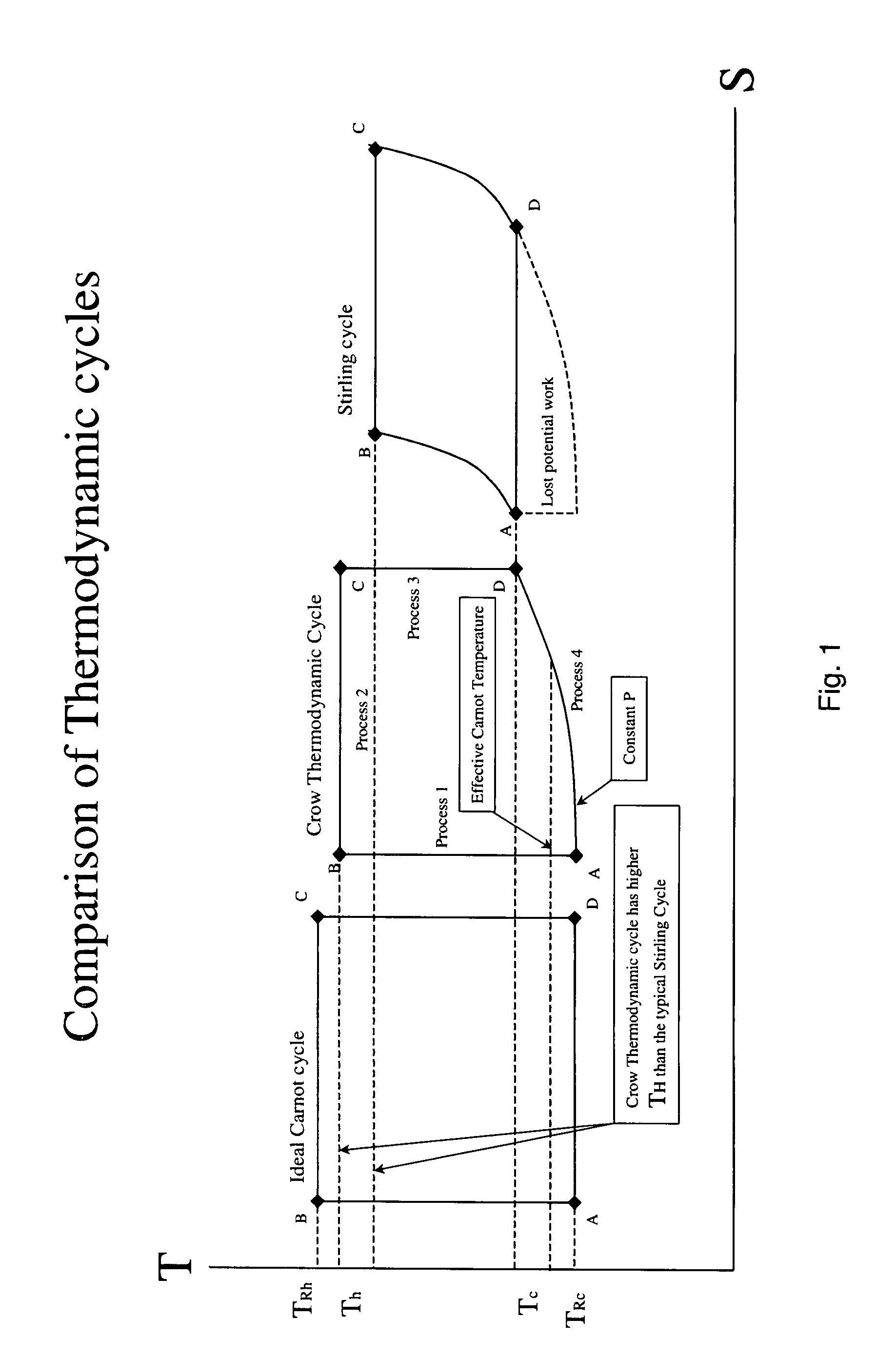
[0009]Several objects and advantages of the present invention are: (1) To provide a method and apparatus for implementing the Crow Thermodynamic Cycle to convert thermal energy to mechanical energy; (2) To provide a method for determining the timing of the expansion of the working fluid and flow through the heat exchanger; (3) To provide a method for using the expansion timing and fluid flows to determine the timing of the cooperating pistons; (4) To provide an engine that can utilize the Crow Thermodynamic Cycle and operate over a wide range of speeds and input temperatures; (5) To provide an engine that automatically adapts its speed to the applied input temperature and shaft load, while still operating on the ideal thermodynamic cycle; (6) To provide an engine design where the exact characteristics of the heat exchanger need not be known; (7) To provide an engine with improved specific power; (8) To provide an engine with greater flexibility in heat exchanger design; (9) To provide an engine design allowing the use of standard poppet-style valves; and (10) To provide an engine that is easy to assemble and disassemble and maintain.
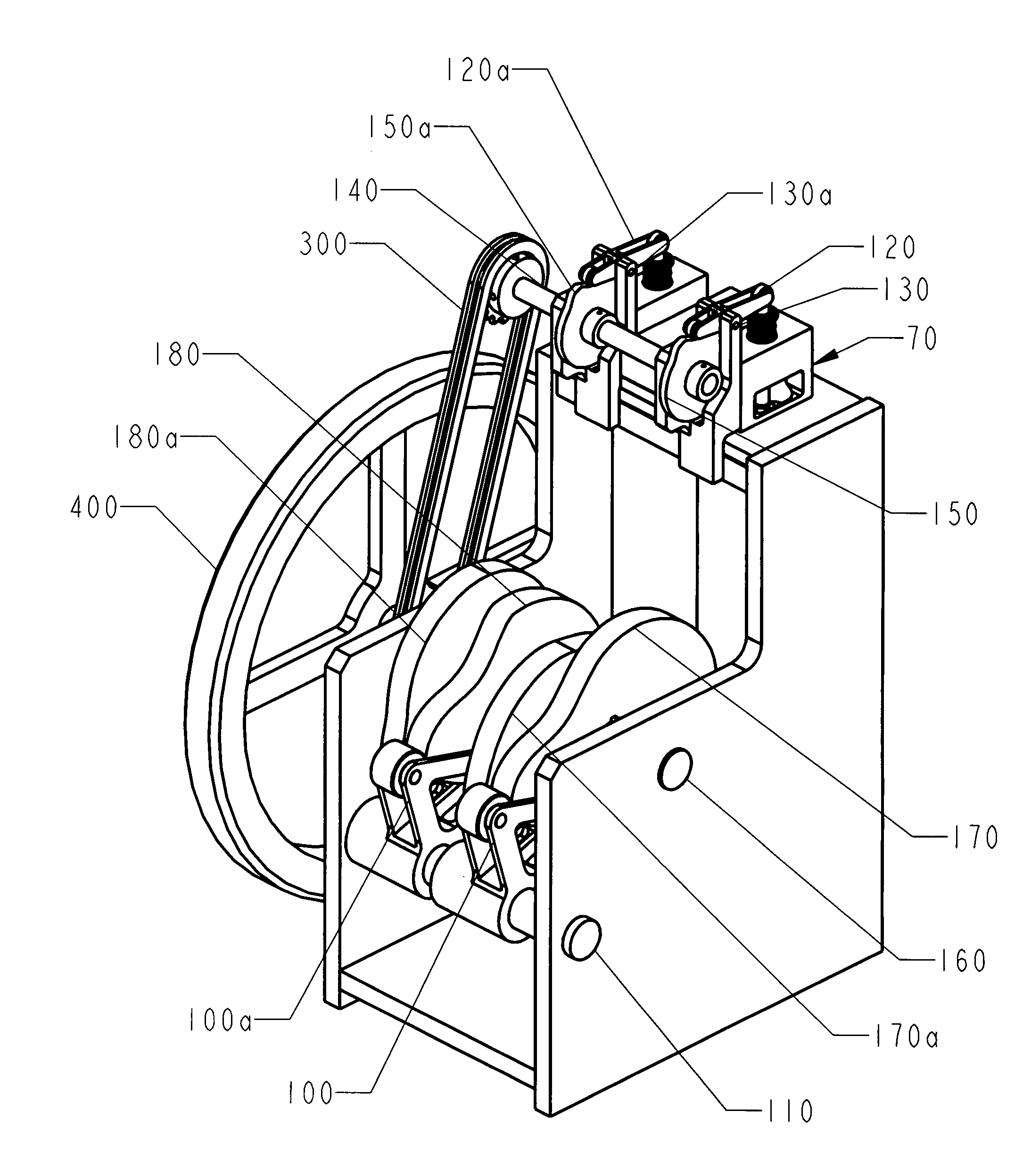
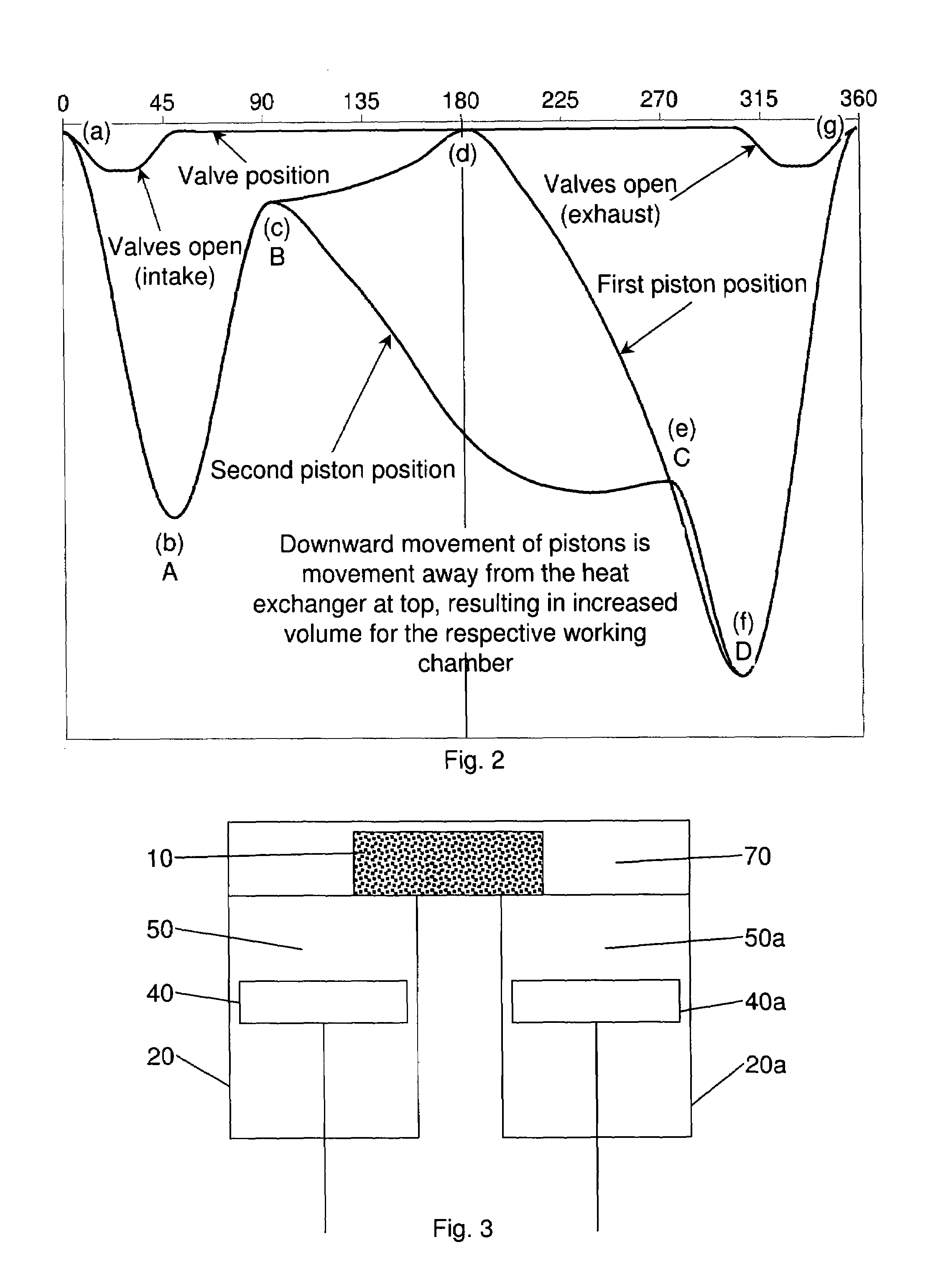
[0010]There is in accordance with the present invention a method and apparatus for converting thermal energy to mechanical energy using the thermodynamic cycle disclosed in U.S. Pat. No. 7,284,372, while allowing for a wide range of operating parameters, automatic and self regulating speed adjustment, great design flexibility and ease of assembly and maintenance.

Problems solved by technology

However, the “Diesel cycle” is known today as constant pressure combustion, as difficulties in achieving internal isothermal combustion resulted in the general abandonment of the former concept.

Method used


Image

  • Thermal engine utilizing isothermal piston timing for automatic, self-regulating, speed control
  • Thermal engine utilizing isothermal piston timing for automatic, self-regulating, speed control
  • Thermal engine utilizing isothermal piston timing for automatic, self-regulating, speed control

Examples


Embodiment Construction

Best Modes for Carrying Out the Invention

[0029]The present disclosure is of an apparatus and method for converting thermal energy into mechanical energy. Reference is made to a thermodynamic cycle that will sometimes be called the “Crow Thermodynamic Cycle,” the “Crow Cycle” or “the subject cycle.” Also in the course of this disclosure reference will be made to a number of mathematical variables. For convenience, the several variables and their corresponding meanings are set forth in Table 1.

[0030]

TABLE 1List of VariablesTcLow temperature reached by the working fluid during thethermodynamic cycleThHigh temperature reached by the working fluid during thethermodynamic cycleTRcCold reservoir temperatureTRhHot reservoir temperatureTBTemperature at thermodynamic state BPAPressure at thermodynamic state APDPressure at thermodynamic state DVAEngine volume at thermodynamic state ACrIsentropic compression ratio of the working fluidErExpansion ratio: ending isothermal volume to beginning isot...


PUM


Abstract

A method and apparatus for converting thermal energy to mechanical energy. Operating on a thermodynamic cycle of isentropic compression, isothermal expansion, isentropic expansion and finally constant pressure cooling and contraction, an external heat engine utilizes a heat exchanger carrying heat from an external energy source to the working parts of the engine. Apparatus and methods are disclosed for engine piston timing, such that during isothermal expansion, each unit angular rotation of a drive shaft results in the capture of a constant, unit amount of working fluid expansion energy. Thus, the amount of energy captured during each unit angular rotation of apparatus drive shaft is a constant. Timing the working fluid expansion and fluid flow assures that the working fluid undergoes isothermal expansion, regardless of the quantum of heat energy applied. The modulation of heat input to the heat exchanger results in an automatic modulation of engine speed.

Description

CROSS-REFERENCE TO RELATED APPLICATIONS[0001]This application claims the benefit of the filing of U.S. provisional application Ser. No. 60 / 801,029, filed on 17 May 2006, and the specification thereof is incorporated herein by reference. This application also is related to utility application Ser. No. 10 / 982,167, filed 4 Nov. 2004, now issued as U.S. Pat. No. 7,284,372, entitled “Method and Apparatus for Converting Thermal Energy to Mechanical Energy,” the entire contents of which is incorporated by reference herein.BACKGROUND OF THE INVENTION[0002]1. Field of the Invention (Technical Field)[0003]The present invention relates to engines, specifically to an engine utilizing an improved method for using external heat to heat a unit mass of working fluid and thereby convert the thermal energy to mechanical energy, where the unit mass is later expelled and a new unit mass of working fluid is introduced to repeat the cycle.[0004]2. Background Art[0005]Rudolf Diesel originally identified a...

Claims


Application Information

Patent Timeline
IPC IPC(8): F01B29/10
CPCF02G1/043F02G2244/52
Inventor CROW, DARBY
Owner CROW DARBY
Learn More