
Combustion generating device of internal combustion engine

Active Publication Date: 2013-06-13
HYUNDAI MOTOR CO LTD
View PDF8 Cites 3 Cited by
  • Summary
  • Abstract
  • Description
  • Claims
  • Application Information

AI Technical Summary

Benefits of technology

The present invention provides a combustion generating device for an internal combustion engine that can precisely control flame and reduce harmful exhaust gas through low-temperature rapid combustion. The device is simple and does not require a prechamber, making it easy to manufacture and improve engine power. It also promotes stability and fuel efficiency by improving combustion stability and reducing failures.

Problems solved by technology

Therefore, the internal combustion engine requires an expensive catalytic filter to reduce the nitrogen oxide.
Further, the prechamber jet ignition system may continuously and stably generate a very large flame kernel.
However, in the above-described internal combustion engine where combustion is performed in the combustion chamber through the flame injected from the prechamber, an accidental fire is highly likely to occur when an ultra small amount of fuel is injected into a small space formed by the prechamber and ignited by the spark plug.
In this case, the engine may be failed.
In addition, the internal combustion engine has difficulties in performing precise ignition control such as air-fuel ratio control or combustion speed control.

Method used


Image

  • Combustion generating device of internal combustion engine
  • Combustion generating device of internal combustion engine
  • Combustion generating device of internal combustion engine

Examples


Embodiment Construction

[0028]Reference will now be made in detail to various embodiments of the present invention(s), examples of which are illustrated in the accompanying drawings and described below. While the invention(s) will be described in conjunction with exemplary embodiments, it will be understood that present description is not intended to limit the invention(s) to those exemplary embodiments. On the contrary, the invention(s) is / are intended to cover not only the exemplary embodiments, but also various alternatives, modifications, equivalents and other embodiments, which may be included within the spirit and scope of the invention as defined by the appended claims.

[0029]Hereinafter, the exemplary embodiments of the present invention will be described in detail with reference to the accompanying drawings.

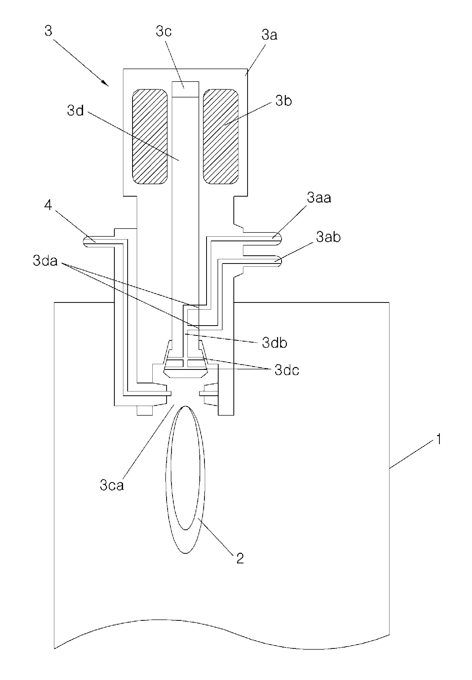
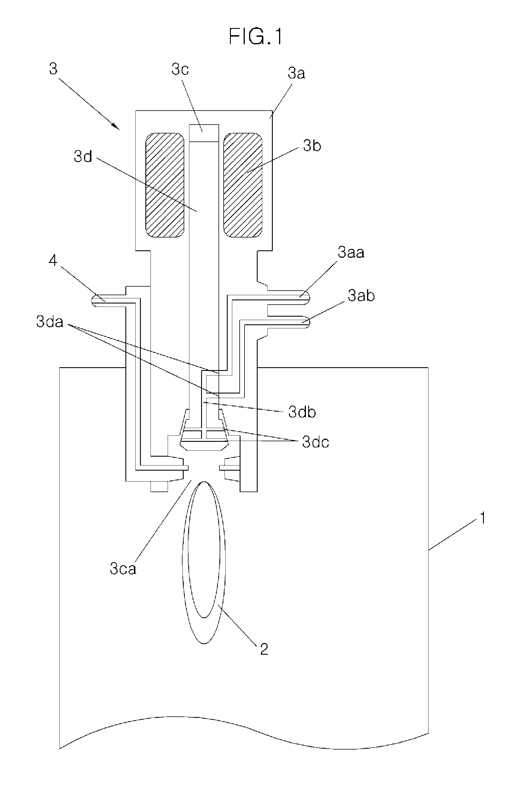
[0030]Referring to FIG. 1, a combustion chamber 1 having a predetermined volume is formed in a cylinder forming an internal combustion engine. Although not illustrated, a fuel injection device s...


PUM


Abstract

Provided is a combustion generating device of an internal combustion engine, which is capable of performing very precise flame control through a simple structure which does not need a prechamber and reducing harmful exhaust gas through low-temperature rapid combustion. The combustion generating device includes: an ignition system generating a spark; and an injector generating a mixture by mixing air and fuel and injecting a flame into a combustion chamber, the flame being generated by applying the spark to the mixture.

Description

CROSS-REFERENCE TO RELATED APPLICATIONS[0001]The present application claims priority to Korean Patent Application Number 10-2011-0133767 filed Dec. 13, 2011, the entire contents of which application is incorporated herein for all purposes by this reference.BACKGROUND OF THE INVENTION[0002]1. Field of the Invention[0003]The present invention relates to a combustion generating device of an internal combustion engine, and more particularly, to a combustion generating device of an internal combustion engine, which directly injects a flame into a combustion chamber, the flame being ignited and generated at the same time as a mixture of air and fuel is injected from a sub injector which mixes the air and fuel and injects the mixture.[0004]2. Description of Related Art[0005]In general, an internal combustion engine using gasoline as fuel, such as an engine of a vehicle, directly injects fuel into a combustion chamber formed in a cylinder block through an injector, and the fuel injected int...

Claims


Application Information

Patent Timeline
IPC IPC(8): F02M51/06
CPCF02M69/045F02B19/12F02M57/06
Inventor WOO, SOOHYUNGKONG, JINKOOKKIM, YOUNGNAM
Owner HYUNDAI MOTOR CO LTD
Learn More