
Pencil-type glow plug having an integrated combustion chamber pressure sensor

a pressure sensor and glow plug technology, applied in lighting and heating apparatus, instruments, specific gravity measurement, etc., can solve the problems of extremely restricted space in the cylinder head of an internal combustion engine, comparatively low-cost pressure sensors make sense, etc., and achieve increased fatigue strength, high strength, and high fatigue strength

Inactive Publication Date: 2009-09-01
ROBERT BOSCH GMBH
View PDF18 Cites 48 Cited by
  • Summary
  • Abstract
  • Description
  • Claims
  • Application Information

AI Technical Summary

Benefits of technology

The present invention relates to a method of determining pressure in the cylinders of a self-igniting internal combustion engine using a combustion chamber pressure sensor integrated into a pencil-type glow plug. The sensor is sealed by a flexible diaphragm made of a stainless, precipitation-hardened maraging steel, which has high strength and fatigue strength under reverse bending stress. The stainless precipitation-hardened maraging steel also has high aging stability, low stress drop, and favorable hysteresis characteristic. The manufacturing process of the diaphragm allows for the formation of thin-walled components with minimal bending radii. The stainless precipitation-hardened maraging steel has good chemical resistance and weldability, which is important for creating the seal of the pencil-type glow plug.

Problems solved by technology

For series production use in the automotive field, however, only comparatively low-cost pressure sensors make sense from the economic point of view.
In cylinder heads of modern internal combustion engines, no additional bores are to be made, because the space conditions, in particular in four-valve internal combustion engines, are extremely restricted, and the course of coolant ducts is fixedly predetermined, causing the space in the cylinder head of an internal combustion engine to be extremely restricted.

Method used


Image

  • Pencil-type glow plug having an integrated combustion chamber pressure sensor
  • Pencil-type glow plug having an integrated combustion chamber pressure sensor
  • Pencil-type glow plug having an integrated combustion chamber pressure sensor

Examples


Embodiment Construction

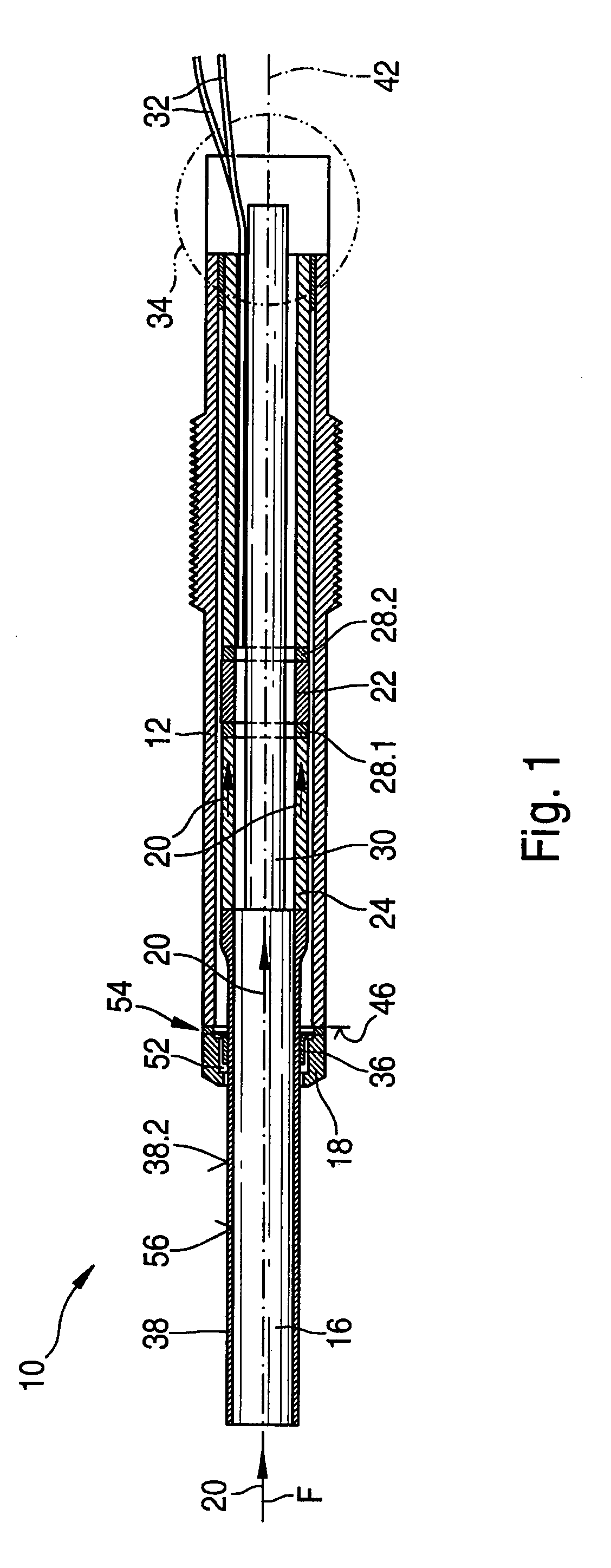
[0012]FIG. 1 shows an example embodiment of the pencil-type glow plug proposed according to the present invention having an integrated combustion chamber pressure sensor, in a sectional representation.

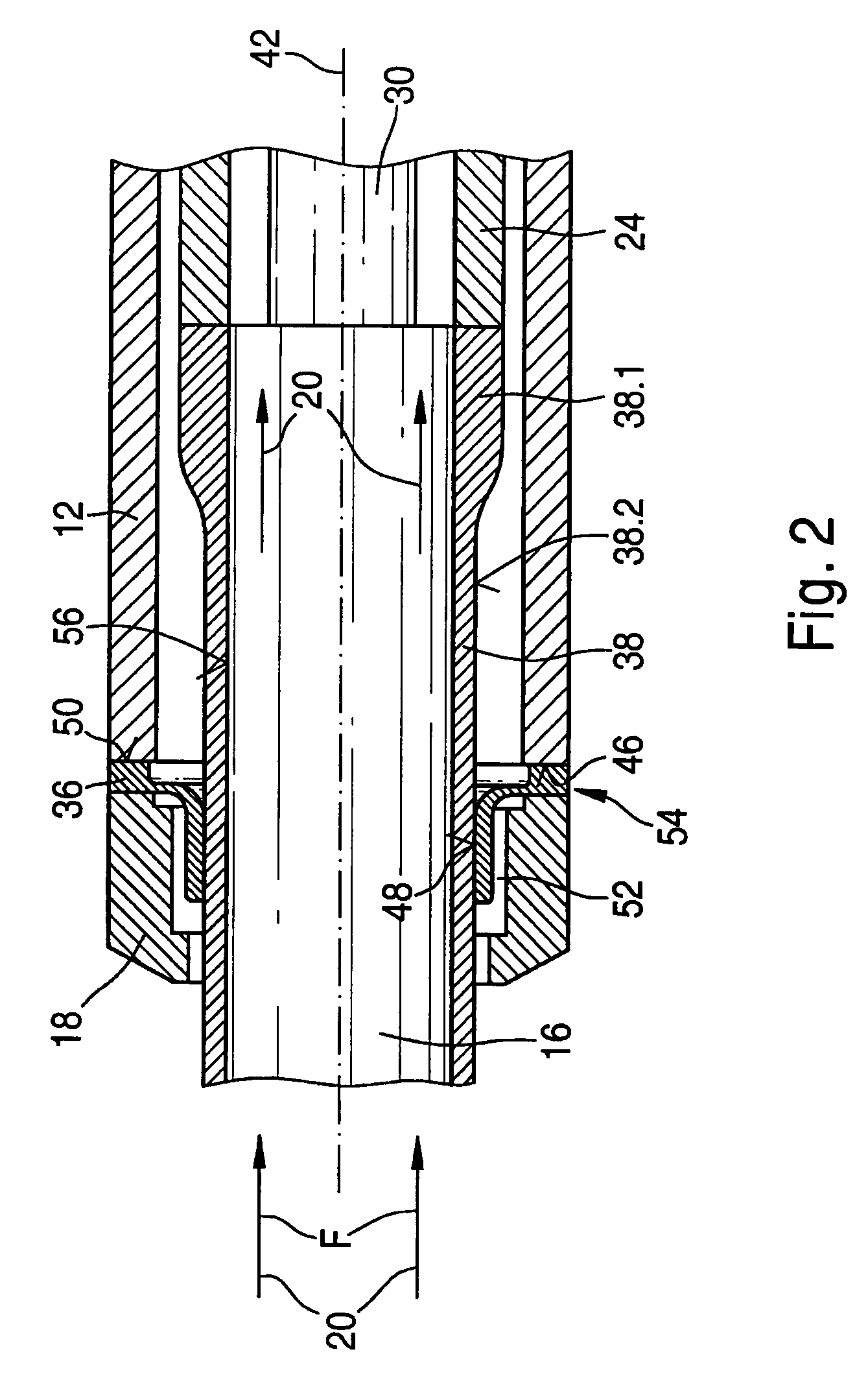
[0013]A pencil-type glow plug 10 has a plug body 12 that acts as a housing. Plug body 12 is generally tubular in construction and encloses a ceramic heating element 16 fashioned in the shape of a bar. The lateral surface of ceramic heating element 16 is identified by reference character 56. Bar-shaped ceramic heating element 16 protrudes at one end from plug body 12, and is sealed via a sealing cone 18. Because an annular gap is provided between ceramic or metallic heating element 16 and sealing cone 18, heating element 16 cannot be sealed. Sealing cone 18 ensures that the compression in the combustion chamber of the internal combustion engine is not reduced by leakage of combustion chamber gases in the area of the pencil-type glow plug bore.

[0014]At a clamping point 54, sealing cone 1...


PUM

PropertyMeasurementUnit
operating temperaturesaaaaaaaaaa
martensite temperature Msaaaaaaaaaa
temperatureaaaaaaaaaa

Abstract

A pencil-type glow plug for a self-igniting internal combustion engine is described. The pencil-type glow plug includes a plug body in which a combustion chamber pressure sensor is integrated, and a bar-shaped heating element that protrudes out from the plug body at one end, into the combustion chamber of the internal combustion engine. A force-measuring element of the combustion chamber pressure sensor is accommodated behind the heating element, which moves axially under the influence of force. The force-measuring element is sealed against combustion chamber gases by a steel diaphragm made of a stainless precipitation-hardened maraging steel.

Description

BACKGROUND INFORMATION[0001]The exhaust gas laws that regulate pollutant emissions of self-igniting internal combustion engines are constantly becoming more stringent. In addition, newly developed engine management systems of internal combustion engines are subject to the requirement that they ensure low fuel consumption and longer lifespan. The optimization of the combustion in the combustion chamber of a self-igniting internal combustion engine is achieved through the use of controlled fuel injection. For this purpose, in an engine control unit based on a combustion chamber pressure signal, a pressure sensor is used that has to meet very high demands with regard to the achievable degree of reliability of the measurement precision, as well as an optimized combustion chamber.[0002]Kraftfahrtechnisches Taschenbuch [Automotive Handbook], 23rd ed., Braunschweig; Wiesbaden, Vieweg 1999, ISBN 3-528-03876-4, page 111, describes an integrated silicon combustion chamber pressure sensor. The...

Claims


Application Information

Patent Timeline
Patent Type & Authority Patents(United States)
IPC IPC(8): G01L23/10
CPCG01L23/22F23Q2007/002
Inventor KERN, CHRISTOPHSCHOTT, STEFFENLEDERMANN, MARKUSSALTIKOV, PAVLO
Owner ROBERT BOSCH GMBH
Learn More