Screen printing apparatus

a screen printing and printing apparatus technology, applied in the field of inspection stations and printing stations, can solve the problems of significant increase in manufacturing complexity, and achieve the effects of accurate printing of deposits, short cycle times, and tight tolerances

Active Publication Date: 2009-08-25
ASM ASSEMBLY SYST SINGAPORE PTE LTD
View PDF12 Cites 15 Cited by
  • Summary
  • Abstract
  • Description
  • Claims
  • Application Information

AI Technical Summary

Benefits of technology

[0011]The present inventors have thus devised the present invention which allows for the accurate printing of deposits of material onto workpieces and does not require the fabrication of workpieces to any tighter tolerances than currently required, and, moreover, does not require features on one, lower surface of a workpiece to have a predetermined registration with elements on the other, upper surface of the workpiece. In the present invention, features on an upper surface of a workpiece to be printed, which have a predetermined and precise relationship to elements thereon, and features on the other, lower surface of the workpiece are both imaged and the positional relationship determined, such that the upper surface of the workpiece, and in particular the elements thereon, can be subsequently precisely positioned at a printing zone by reference only to features on the lower surface of the workpiece. Also, the present invention is particularly flexible in not requiring features on one, lower surface of a workpiece to have a predetermined registration with elements on the other, upper surface of the workpiece.
[0012]In this way, the present invention provides a screen printing apparatus for and method of screen printing which provide for shorter cycle times and the improved alignment of a workpiece and the printing screen.

Problems solved by technology

Such tolerance requirements would significantly increase the manufacturing complexity, and be for no reason other than to provide for the precise registration of features on one, lower surface of the workpiece to elements on the other, upper surface of the workpiece.

Method used


Image

  • Screen printing apparatus
  • Screen printing apparatus
  • Screen printing apparatus

Examples


Embodiment Construction

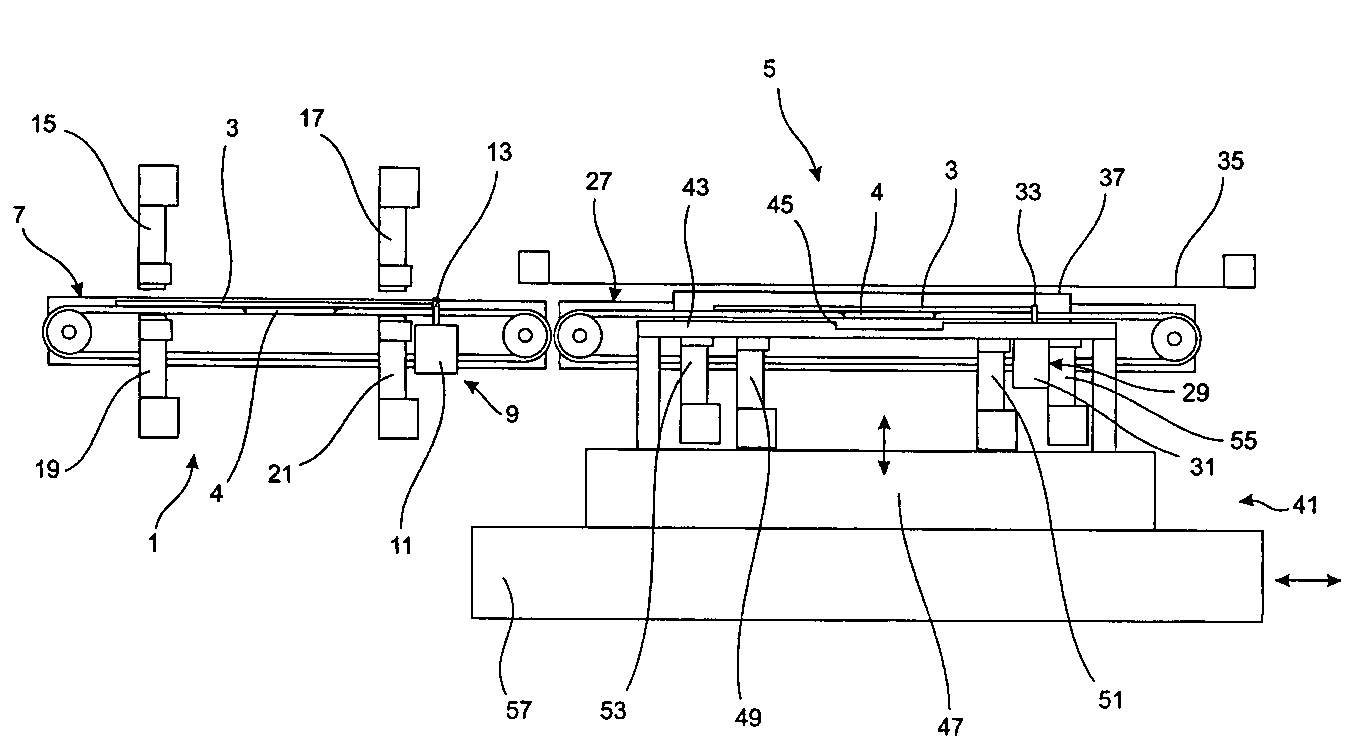
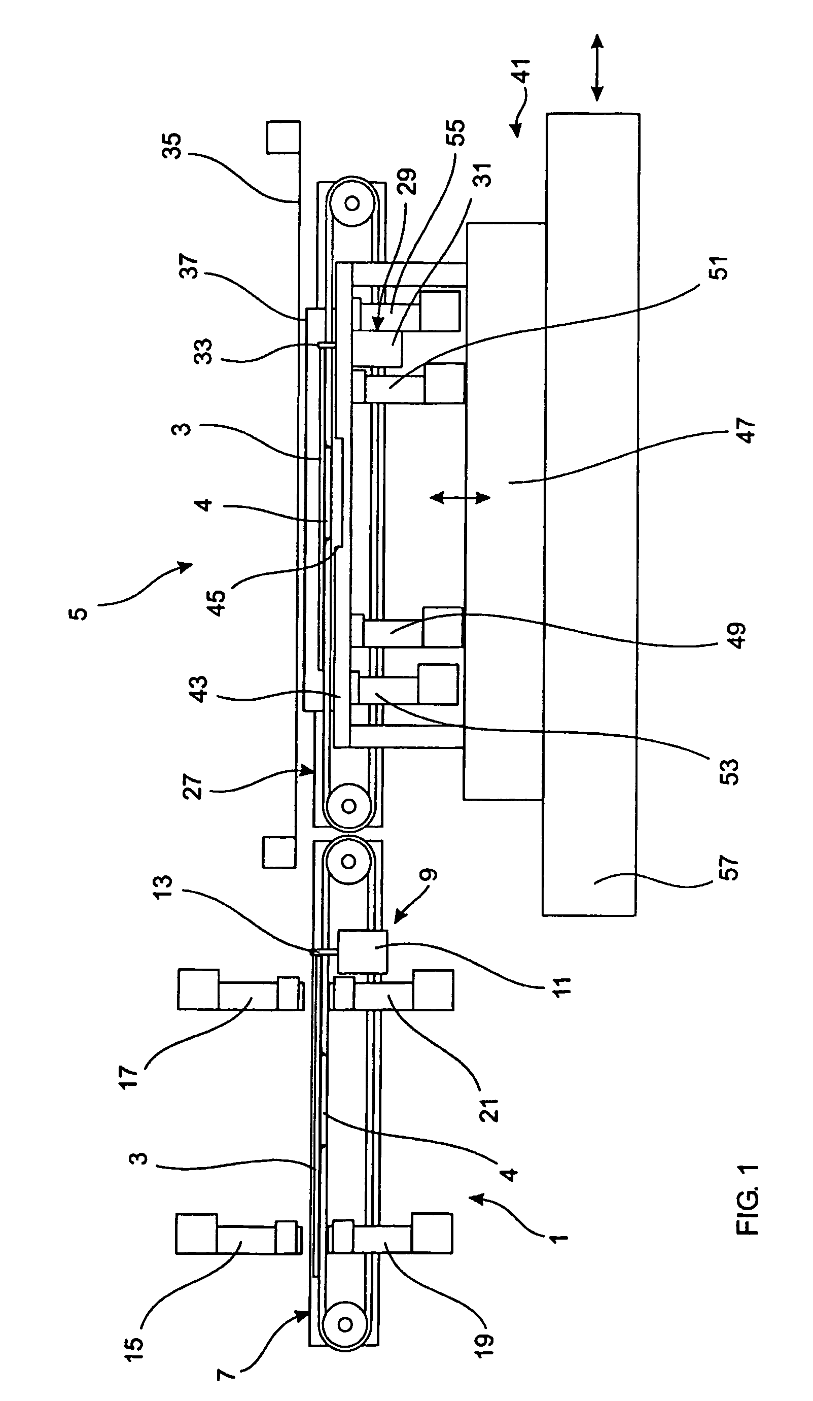
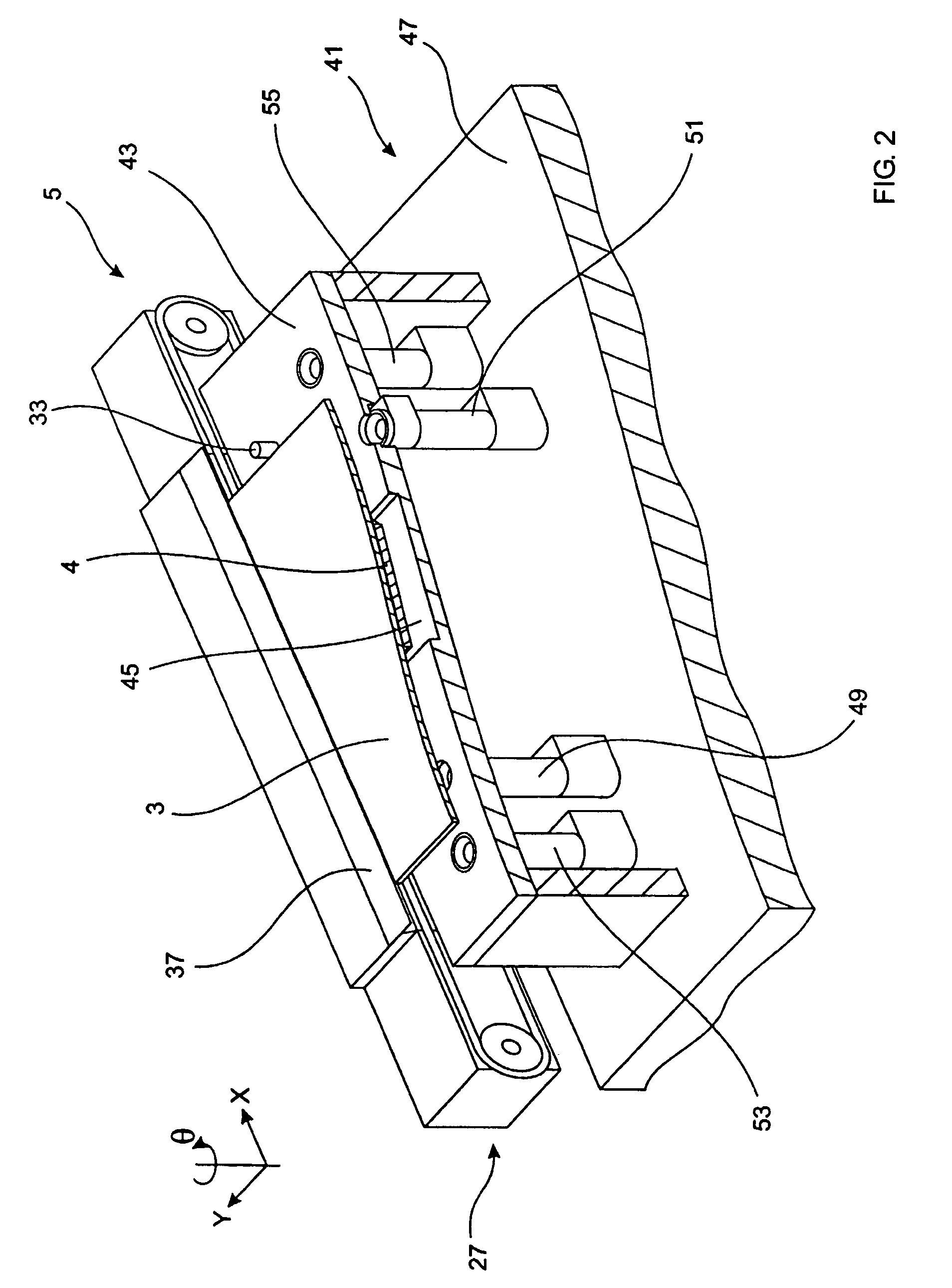
[0078]The screen printing apparatus comprises an inspection station 1 to which a workpiece 3, in this embodiment a printed circuit board, having a component 4 mounted to the lower surface thereof is delivered for optical inspection, and a printing station 5, which is located downstream of the inspection station 1, to which a workpiece 3 is delivered, in this embodiment from the inspection station 1, for the printing of material deposits thereon.

[0079]The inspection station 1 comprises a transport mechanism 7 for receiving a workpiece 3 and transporting the workpiece 3 first to an inspection zone and subsequently to the printing station 5, and an inspection stop 9 for stopping a workpiece 3 at the inspection zone.

[0080]In this embodiment the transport mechanism 7 comprises a belt feed unit, as commonly used in the electronics field for transporting printed circuit boards. In a preferred embodiment, again as in this embodiment, the transport mechanism 7 comprises a pair of driven belt...


PUM


Abstract

A screen printing apparatus and method for printing deposits of material onto a workpiece, the apparatus comprising an inspection station for determining a positional relationship of features on upper and lower surfaces of the workpiece. The inspection station comprises an imaging system for determining a positional relationship of features on upper and lower surfaces of the workpiece. The imaging system comprises at least two spaced imaging units for imaging features on an upper surface of the workpiece and at least two spaced imaging units for imaging features on a lower surface of the workpiece. A processing unit determines a positional relationship of the imaged features on the upper and lower surfaces of the workpiece. A printing station prints deposits of material onto the workpiece. Also described are a transport mechanism and an alignment system.

Description

[0001]This application is a national phase of International Application No. PCT / GB02 / 03175 filed Jul. 10, 2002 and published in the English language.BACKGROUND OF THE INVENTION[0002](1) Field of the Invention[0003]The present invention relates to an inspection station and a printing station, in particular for a screen printing apparatus, a screen printing apparatus incorporating the same, and a method of screen printing deposits of material onto workpieces, in particular substrates, through a printing screen, often referred to as a stencil.[0004]The present invention finds particular application in the electronics field in printing deposits of solder paste onto printed circuit boards prior to the subsequent placement of electronic components.[0005](2) Description of the Related Art[0006]In printing material onto workpieces, particularly solder paste onto contact pads of a printed circuit board, it is important to accurately align the workpiece with the printing screen through which ...

Claims


Application Information

Patent Timeline
Patent Type & Authority Patents(United States)
IPC IPC(8): G06K9/00G06K9/32H04N7/18B41F15/08B41F15/26H05K3/12
CPCB41F15/0818H05K3/1216B41F15/26B41P2215/114
Inventor MCEVOY, IAN PATRICKSQUIBB, FRANK NORMAN
Owner ASM ASSEMBLY SYST SINGAPORE PTE LTD
Why Eureka
Try Eureka