
Memory refresh method and system

a technology of memory refresh and memory, applied in the field of memory refresh methods and devices, can solve problems such as power consumption increasing accordingly

Active Publication Date: 2009-08-25
VIA TECH INC
View PDF5 Cites 20 Cited by
  • Summary
  • Abstract
  • Description
  • Claims
  • Application Information

AI Technical Summary

Problems solved by technology

Usually, as capacity of a system memory increases, power consumption increases accordingly.

Method used


Image

  • Memory refresh method and system
  • Memory refresh method and system
  • Memory refresh method and system

Examples


Embodiment Construction

[0011]The following description is of the best-contemplated mode of carrying out the invention. This description is made for the purpose of illustrating the general principles of the invention and should not be taken in a limiting sense. The scope of the invention is best determined by reference to the appended claims.

[0012]To maintain data in a system memory, the system memory must refresh periodically, either by self-refresh or auto-refresh mode, either of which refreshes all memory ranks simultaneously.

[0013]Based on the definition of JEDEC, the system memory in the auto-refresh mode performs the auto-refresh every steady refresh period TREF. A timer is usually configured in a memory system for setting the refresh period TREF, such as 7.8 microseconds.

[0014]Additionally, based on the definition of JEDEC, system memory performs self-refresh when the computer system is in a power down state or a sleep state. That is, self-refresh is performed only if all the memory ranks are at an ...


PUM


Abstract

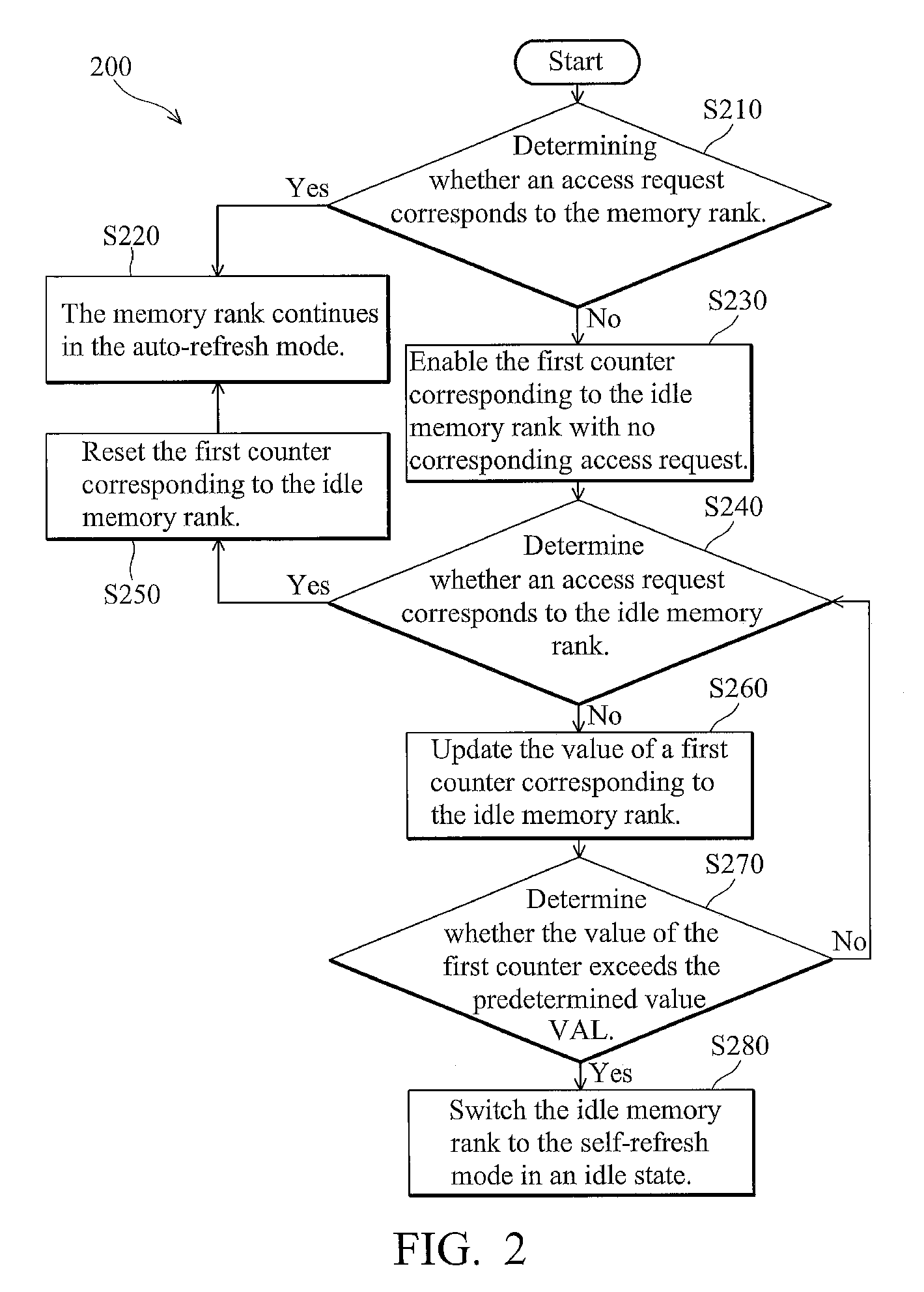
A memory refresh method applicable in a system memory is disclosed. The memory system comprises a plurality of memory ranks. It is to determine whether an access request corresponds to the memory rank, and an idle auto-refresh number of the memory rank is calculated if there is no access request corresponds to the memory rank. The memory rank is switched from an auto-refresh mode to a self-refresh mode when the idle auto-refresh number of the memory rank reaches a predetermined value.

Description

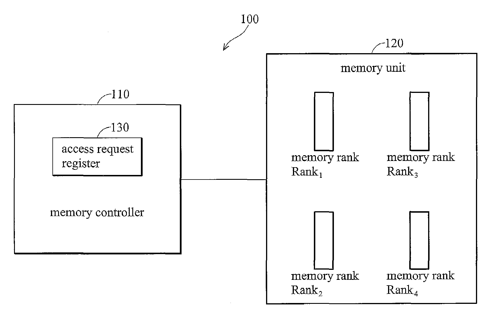
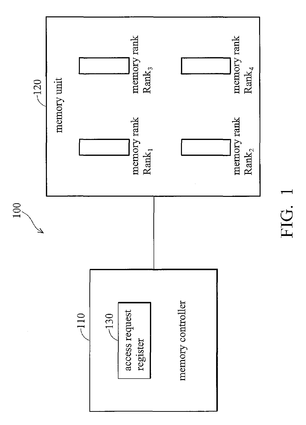
BACKGROUND OF THE INVENTION[0001]1. Field of the Invention[0002]The invention relates to memory refresh methods and devices, and in particular to the methods and devices to switch each memory rank of a memory to a self-refresh mode respectively.[0003]2. Description of the Related Art[0004]A system memory stores data from a central processing unit (CPU) and various peripheral components. Usually, as capacity of a system memory increases, power consumption increases accordingly. One commonly used system memory is a dynamic random access memory (DRAM), embodies as a single in-line memory module (SIMM) or dual in-line memory module, (DIMM), with channels referred to as memory ranks. Memory usually comprises a plurality of memory banks, each comprising multiple memory cells arranged in arrays.BRIEF SUMMARY OF INVENTION[0005]Disclosed is a memory refresh method applied in a system memory. The system memory comprises a plurality of memory ranks. It is to determine whether an access request...

Claims


Application Information

Patent Timeline
Patent Type & Authority Patents(United States)
IPC IPC(8): G11C7/00
CPCG06F13/1636Y02B60/1228Y02D10/00
Inventor YANG, FANLIN, CHING-HSIANGDING, JIE
Owner VIA TECH INC
Learn More