Interactive debug system for multiprocessor array

Active Publication Date: 2009-08-18
IMAGINATION TECH LTD
View PDF9 Cites 11 Cited by
  • Summary
  • Abstract
  • Description
  • Claims
  • Application Information

AI Technical Summary

Problems solved by technology

An error occurs when an actual result does not match an expected result, and can be caused by errors in the software and / or hardware.

Method used


Image

  • Interactive debug system for multiprocessor array
  • Interactive debug system for multiprocessor array
  • Interactive debug system for multiprocessor array

Examples


Embodiment Construction

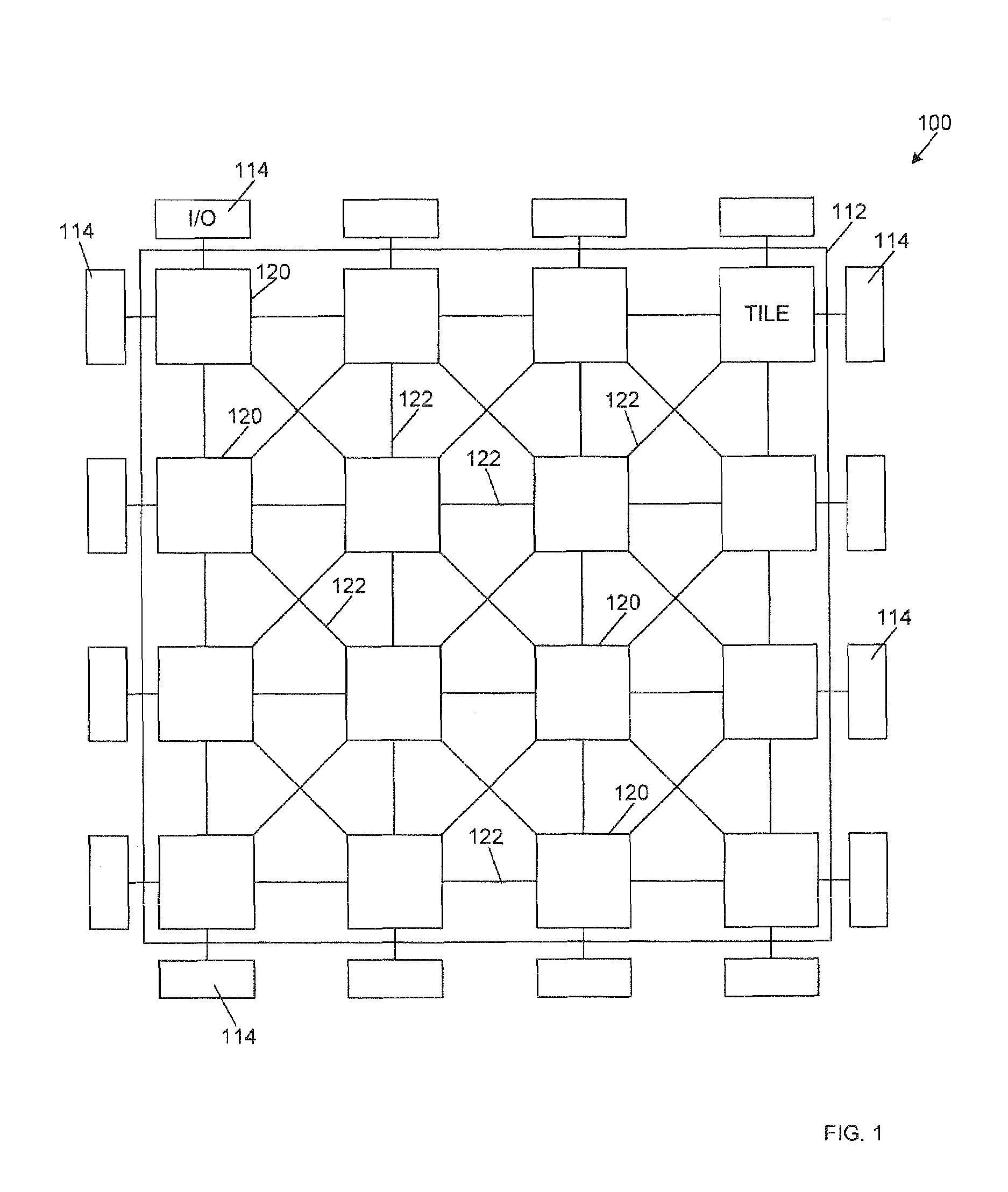
[0017]FIG. 1 illustrates an example tessellated multi-element processor platform 100 according to embodiments of the invention, Central to the processor platform 100 is a core 112 of multiple tiles 120 that are arranged and placed according to available space and size of the core 112. The tiles 120 are interconnected by communication data lines 122 that can include protocol registers as described below.

[0018]Additionally, the platform 100 includes Input / Output (I / O) blocks 114 placed around the periphery of the platform 100. The I / O 114 blocks are coupled to some of the tiles 120 and provide communication paths between the tiles 120 and elements outside of the platform 100. Although the I / O blocks 114 are illustrated as being around the periphery of the platform 100, in practice the blocks 114 may be placed anywhere within the platform 100. Standard communication protocols, such as Periphery Component Interface Express (PCIe), Dynamic Data Rate Two Synchronous Dynamic Random Access ...


PUM


Abstract

A debug network on a multiprocessor array includes communication channels, a master controller, and one or more individual debug units in communication with one or more of the processors. The master controller solicits information from the debug units by sending messages along the communication channels. The debug units can control some aspects of the processors, and can simply report on other aspects. By using commands to invoke processor action, then accessing the result, interactive debugging of a multiprocessor array is possible.

Description

CROSS REFERENCE TO RELATED APPLICATIONS[0001]This application is a continuation-in-part of co-pending U.S. application Ser. No. 10 / 871,347, filed Jun. 18, 2004, entitled DATA INTERFACE FOR HARDWARE OBJECTS, which in turn claims the benefit of U.S. provisional application 60 / 479,759, filed Jun. 18, 2003, entitled INTEGRATED CIRCUIT DEVELOPMENT SYSTEM. Additionally this application claims the benefit of U.S. provisional application 60 / 790,912, filed Apr. 10, 2006, entitled MIMD COMPUTING FABRIC, and of U.S. provisional application 60 / 839,036, filed Aug. 20, 2006, entitled RECONFIGURABLE PROCESSOR ARRAY, and of U.S. provisional application 60 / 850,078, filed Oct. 8, 2006, entitled RECONFIGURABLE PROCESSOR ARRAY AND DEBUG NETWORK. The teachings of all of these applications are explicitly incorporated by reference herein.TECHNICAL FIELD[0002]This disclosure relates to a system debugger, and, more particularly, to a system debugger structured to operate on a multiprocessor platform.BACKGRO...

Claims


Application Information

Patent Timeline
IPC IPC(8): G06F11/00
CPCG06F17/5045G06F11/362G06F30/30
Inventor JONES, ANTHONY MARKWASSON, PAUL M.WHITE, EDMUND H.
Owner IMAGINATION TECH LTD
Why Eureka
Try Eureka