
Fumed metal oxide particles and process for producing the same

a technology of metal oxide particles and process, applied in the field of metal oxide particles, can solve the problems of expensive post-production treatment steps

Active Publication Date: 2009-08-11
CABOT CORP
View PDF72 Cites 9 Cited by
  • Summary
  • Abstract
  • Description
  • Claims
  • Application Information

AI Technical Summary

Benefits of technology

The invention is about a process for making fumed metal oxide particles by atomizing a liquid feedstock in a combustion gas stream. The process results in particles that have a specific size and shape. The invention also provides a population of fumed silica particles with specific size ranges. The technical effect of this invention is the ability to produce consistent and high-quality fumed metal oxide particles with controlled size ranges.

Problems solved by technology

While such processes yield metal oxide particles of satisfactory quality, they often involve expensive post-production treatment steps, such as removing the acid that results from the combustion of the halogenated feedstock.

Method used


Image

  • Fumed metal oxide particles and process for producing the same
  • Fumed metal oxide particles and process for producing the same

Examples


examples 1-4

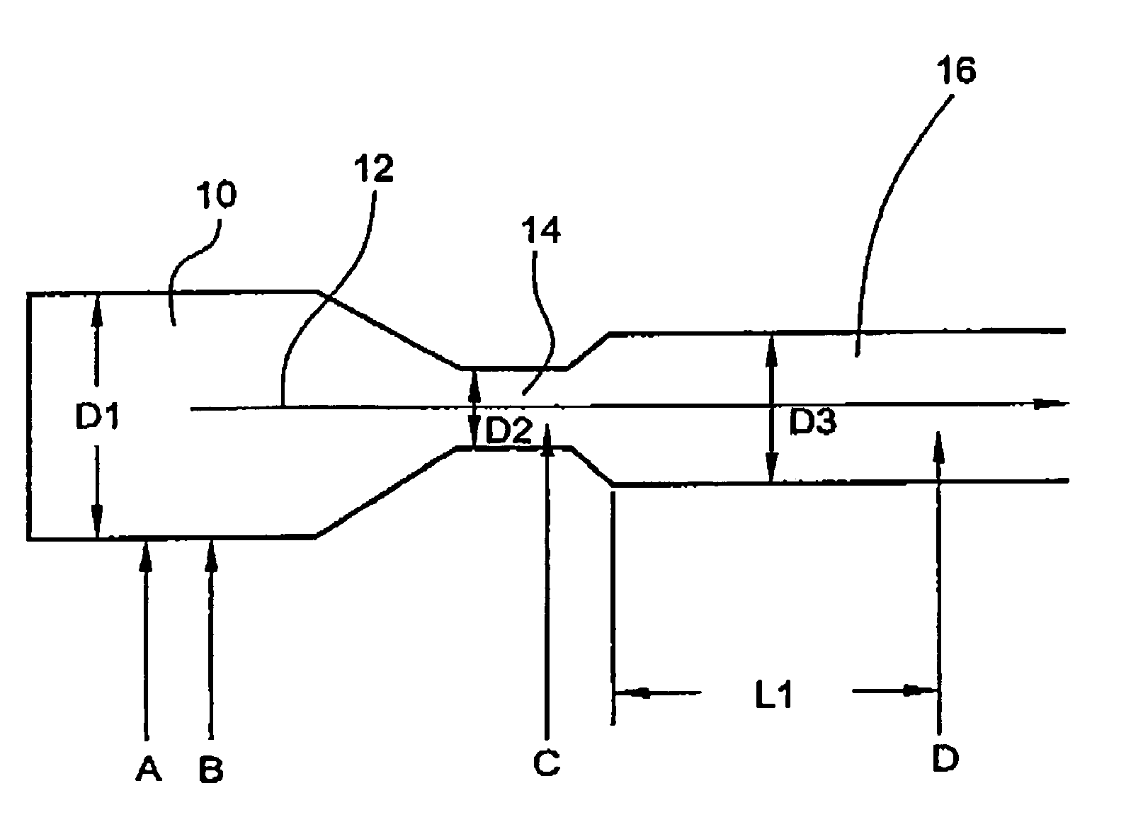
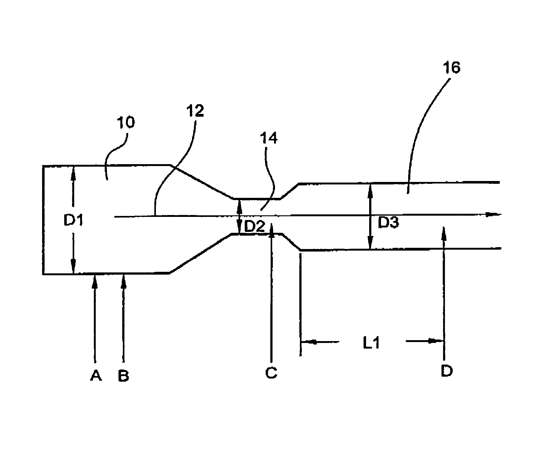
[0037]These examples demonstrate the process of producing fumed metal oxide particles according to the invention. In particular, these examples demonstrate four processes used to produce fumed silica particles having different surface areas. The following processes were carried out using a pilot scale reactor as described above and as depicted in FIG. 1. The approximate dimensions of the pilot scale reactor, with reference to FIG. 1, were as follows: D1=18.4 cm, D2=9.7 cm, D3=69 cm, and L1=213 cm. The liquid feedstock was a commercially available octamethylcyclotetrasiloxane (OMTS), and the stream of combustion gas was established by combusting a mixture of air and natural gas. The quantities of air, natural gas, and OMTS utilized in each of the processes are set forth in Table 1. The liquid feedstock (i.e., OMTS) was injected into the stream of combustion gas at the constricted portion 14 of the reactor (i.e., the portion with diameter D2in FIG. 1), and the reaction mixture was que...

example 5

[0042]This example demonstrates the unique particle size features of the fumed silica particles of the invention. The fumed silica particles of Examples 1-4 were analyzed in accordance with the methods described herein to determine the primary particle sizes d and the aggregate sizes Dcirc for 2000 aggregates from each sample of the fumed silica particles (i.e., the silica particles produced by each of Examples 1-4). The average of the primary particle sizes dave, the average of the aggregate sizes Dcirc ave, and the geometric standard deviation of the aggregate sizes σg (Dcirc) then were calculated. In particular, the average of the primary particle sizes dave of the fumed silica particles was determined using the BET surface area (SA) measurements and the equation: dave (nm)=1941 / SA (m2 / g). Aggregate size Dcirc was determined using TEM image analysis to measure the area, A, of each aggregate and calculating the aggregate size Dcirc using the equation Dcirc=√{square root over (4A / π...


PUM

PropertyMeasurementUnit
temperatureaaaaaaaaaa
solidifying temperatureaaaaaaaaaa

Abstract

The invention provides a process for producing fumed metal oxide particles comprising providing a stream of a liquid feedstock comprising a volatizable, non-halogenated metal oxide precursor, providing a stream of a combustion gas having a linear velocity sufficient to atomize and combust or pyrolyze the liquid feedstock, and injecting the stream of the liquid feedstock into the stream of combustion gas to form a reaction mixture such that the liquid feedstock is atomized and subjected to a sufficient temperature and residence time in the combination gas stream for fumed metal oxide particles to form before the combustion gas temperature is reduced below the solidifying temperature of the metal oxide particle. The invention further provides fumed silica particles having a relatively small aggregate size and / or narrow aggregate size distribution.

Description

CROSS-REFERENCE TO RELATED APPLICATIONS[0001]This patent application claims the benefit of U.S. Provisional Patent Application No. 60 / 429,217, filed Nov. 26, 2002.FIELD OF THE INVENTION[0002]This invention pertains to metal oxide particles and processes for the production thereof.BACKGROUND OF THE INVENTION[0003]Metal oxide particles have found widespread applications in industry. For example, in the semiconductor industry, metal oxide particles have been used as abrasives in polishing compositions. Metal oxide particles also have been used in the preparation of coating compositions, such as paints, and in the production of ink recording media.[0004]Various methods have been disclosed for the production of metal oxide particles. For example, U.S. Pat. No. 3,322,499 (Carpenter et al.) discloses a method for the production of pyrogenic metal oxide particles by high-temperature oxidation of volatile metal compounds, such as metal halides or oxyhalides. While such processes yield metal ...

Claims


Application Information

Patent Timeline
Patent Type & Authority Patents(United States)
IPC IPC(8): C01B33/12C01B13/20C01B13/24C01B13/30C01B33/18
CPCB82Y30/00C01B13/20C01B13/24C01B13/30C01B33/183C01P2006/12C01P2002/60C01P2004/50C01P2004/62C01P2004/64
Inventor KUTSOVSKY, YAKOV E.
Owner CABOT CORP
Learn More