Electron spectrometer

a technology of electron spectrometer and electron microscope, which is applied in the field of electron microscope and photoelectron microscope, can solve the problems of low energy resolution, low noise, and difficulty in transferring electrons from the imaging lens system, and achieve the effect of not being able to image high energy electrons with chemical specificity

Inactive Publication Date: 2009-08-04
BROWNING RAYMOND
View PDF12 Cites 5 Cited by
  • Summary
  • Abstract
  • Description
  • Claims
  • Application Information

AI Technical Summary

Benefits of technology

[0017]FIG. 4 illustrates the effects of angular distribution on the trajectories of electrons leaving a sample surface in a magnetic field;

Problems solved by technology

Although this is a straightforward technique the problem is that it is intrinsically noisy and of low energy resolution.
However, there is a problem with this approach.
It is difficult to transfer the electrons from the imaging lens system into the energy analysis system and preserve the image.
Hirose used a pulsed X-ray source and a pulsed electronic gating method to only image slower electrons but this necessarily means the high energy electrons that have chemical specificity cannot be imaged.
However, none of these systems has a spatial resolution significantly below 5 microns.
The high energy photoelectrons containing much of the chemically specific information that includes both elemental and chemical state are difficult to image at a high spatial resolution.

Method used


Image

  • Electron spectrometer
  • Electron spectrometer
  • Electron spectrometer

Examples


Embodiment Construction

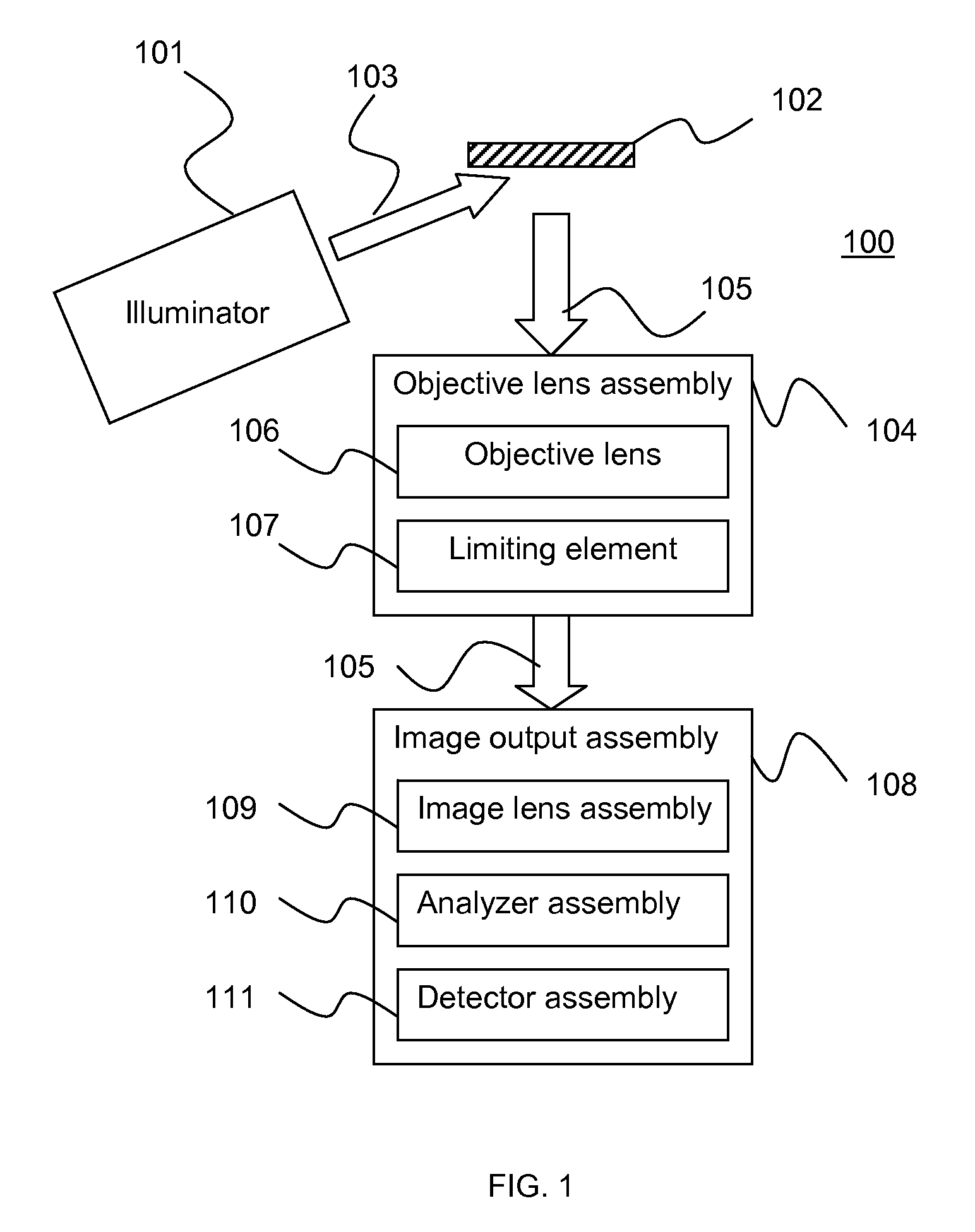
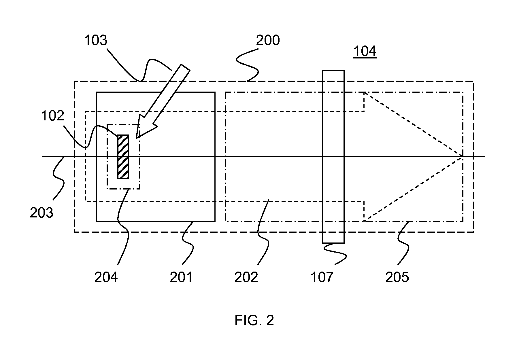
[0038]Referring to FIGS. 1 through 23, wherein like reference numerals refer to like components in the various views, there is illustrated therein a new and improved electron optical apparatus.

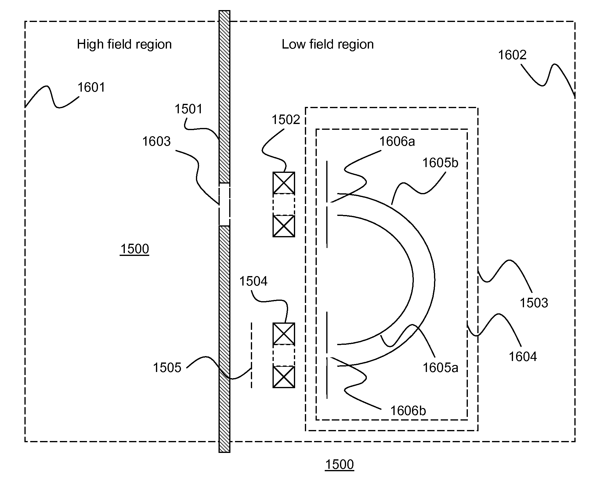
[0039]It is an object of the invention to provide a projection electron lens apparatus with a high spatial resolution. It is a further object of the invention to provide a high spatial resolution photoelectron microscope apparatus. It is a further object of the invention to provide a high spatial resolution photoelectron microscope apparatus with energy resolved imaging. It is a further object of the invention to provide an electron optical device that limits the cyclotron orbit radii within a magnetic field. It is a further object of the invention to provide a projection magnetic field using a permanent magnet device.

[0040]The invention described herein is contained in several functional elements and sub-elements individually and combined together to form the elements of an electron microscop...


PUM


Abstract

A field terminating imaging electron spectrometer being used for imaging electrons created within a magnetic field such as an image produced with a magnetic projection lens in a photoelectron microscope. The preferred embodiment is a CHA with magnetic input and output lenses.

Description

TECHNICAL FIELD[0001]The present invention relates generally to electron optics, and more particularly to electron microscopes, and more particularly to a photoelectron microscope, and more particularly to a photoelectron microscope with a magnetic projection lens, and more particularly to a magnetic projection lens having a cyclotron orbit radii filter, and more particularly to a cyclotron orbit radii filter being composed of a grid having apertures defining the spatial resolution of the projection lens. In another aspect of the invention the magnetic projection lens has a magnetic field which is terminated by a magnetic plate with an aperture. In another aspect of the invention the electrons exiting the magnetic projection lens through the aperture are focused into an energy analyzer using an electron optical lens, and more particularly an energy band pass analyzer, and more particularly a concentric hemispherical analyzer, and more particularly a magnetic electron optical lens. T...

Claims


Application Information

Patent Timeline
Patent Type & Authority Patents(United States)
IPC IPC(8): H01J49/44
CPCH01J37/073H01J37/143H01J37/244H01J37/26H01J2237/24485H01J2237/057H01J2237/06333H01J2237/14
Inventor BROWNING, RAYMOND
Owner BROWNING RAYMOND
Why Eureka
Try Eureka