Vector Potential Photoelectron Microscope

a photoelectron microscope and vector potential technology, applied in the field of electron microscopy, can solve the problems of no prior art that suggests that the magnetic vector potential field, the vector potential field, can be used in photoelectron microscopy, and no prior art that uses the vector potential field in photoelectron microscopy, so as to reduce the magnitude of the vector potential field

Inactive Publication Date: 2012-11-29
BROWNING RAYMOND
View PDF3 Cites 1 Cited by
  • Summary
  • Abstract
  • Description
  • Claims
  • Application Information

AI Technical Summary

Benefits of technology

[0012]It is an object of the invention to provide a method and an instrument utilizing the properties of the vector potential field for photoelectron microscopy. Accordingly the invention is characterized by, a means to create photoelectrons, a means to create a vector potential field as a spatial reference for said photoelectrons emitted from a sample surface, and a means to image said photoelectrons. More specifically a photoelectron imaging apparatus comprising; a vector potential field of substantially uniform curl for producing a spatial reference, a sample immersed in said vector potential field, a source of photons for illuminating said sample and producing photoelectrons, an substantially electron transparent field reducing means for substantially reducing the magnitude of said vector potential field over a substantially short distance, and permitting the exit of said photoelectrons from said vector potential field, providing an imaging means to image said photoelectrons, whereby an image is formed by said photoelectrons emitted from said sample surface.

Problems solved by technology

While there are numerous types of PEM in the literature with a substantial body of patented art, no art exists that suggest that the magnetic vector potential field, also known as the vector potential field, can be used in photoelectron microscopy.
However, there is no prior art that uses the vector potential field in photoelectron microscopy.

Method used


Image

  • Vector Potential Photoelectron Microscope
  • Vector Potential Photoelectron Microscope
  • Vector Potential Photoelectron Microscope

Examples


first embodiment

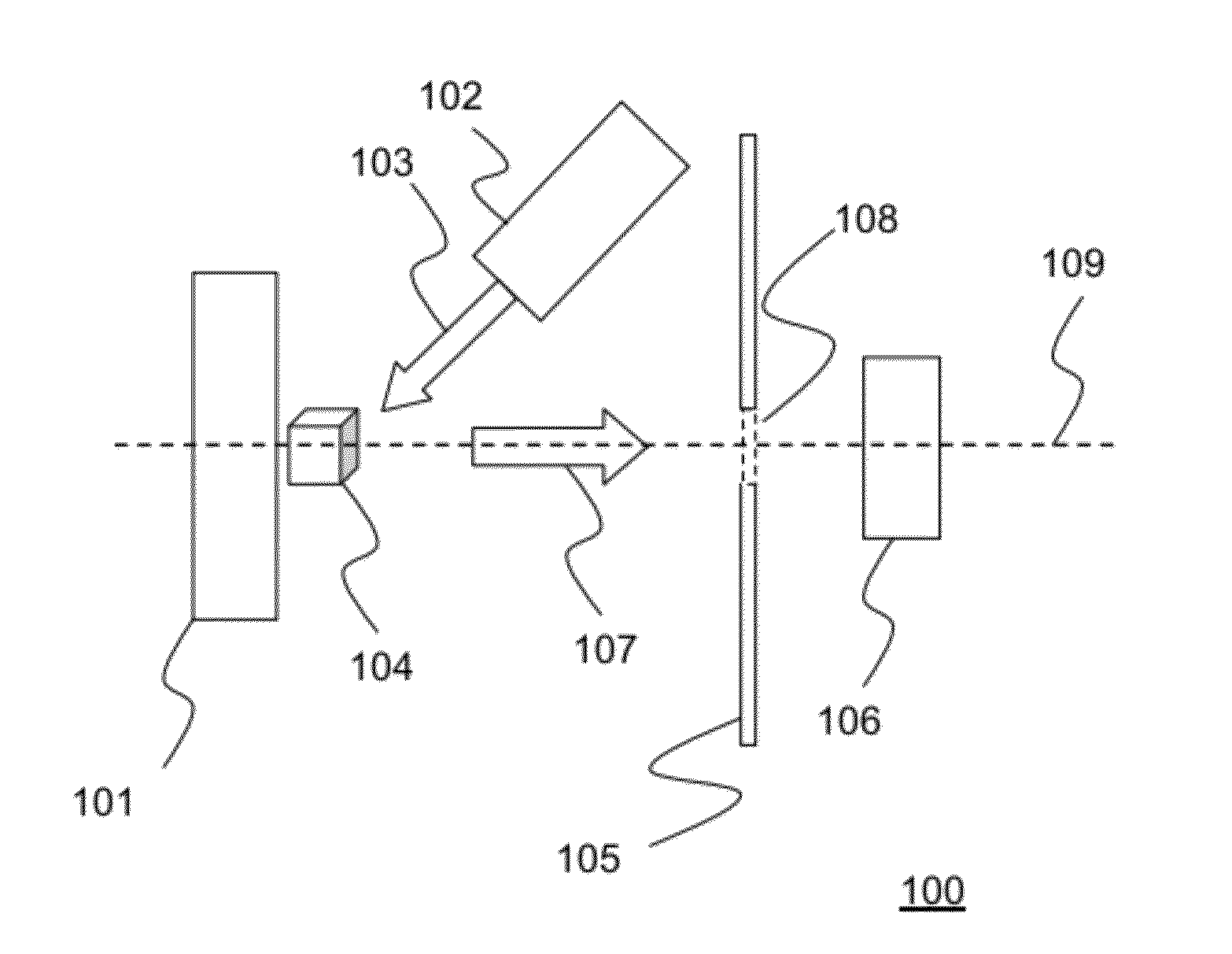
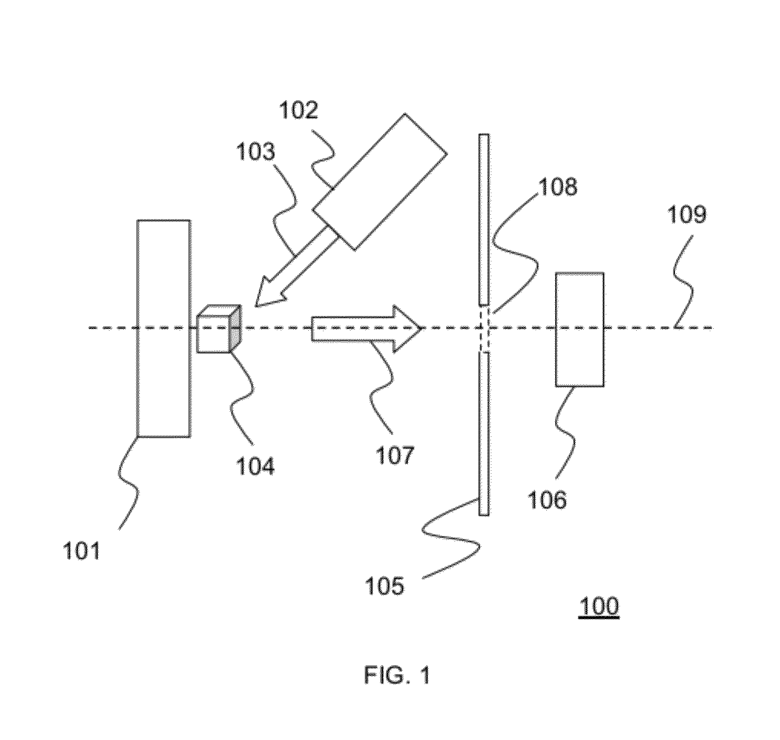
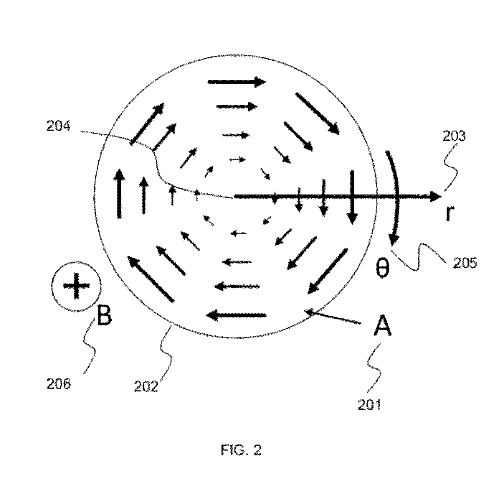
[0028]FIG. 3 illustrates the invention. The fixed field strength vector potential microscope 300 is substantially rotationally symmetric along the optic axis 109. A ferromagnetic assembly 301 composed of ferromagnetic parts including a magnet 302 is utilized as a field generator 101. A specimen 303 is placed directly in front of the ferromagnetic assembly 301 on the optic axis 109 so that the vector potential field A 200 is both at its strongest, and has approximately constant curl across the specimen. A ferromagnetic enclosure 304 surrounds the ferromagnetic assembly 301. The front face 305 of the ferromagnetic enclosure 304 acts as a field reducer 105 along the optic axis 109. The front face 305 has an aperture 108 on the optic axis 109 so that photoelectrons can reach the image detector 106. A source of photoelectrons 102 illuminates the specimen 303 though a second aperture 306 in the ferromagnetic enclosure 304.

[0029]FIG. 4 is a plot 400 of theoretical electron trajectories 401...

third embodiment

[0032]the vector potential microscope 100 is illustrated in FIG. 7. The aperture 108 acts as a pinhole lens. A detector comprising a concave grid 701 and a concave phosphor 702 detects electrons of a high energy by retarding the photoelectrons with the first grid 701, and subsequently accelerating the high energy photoelectrons onto the phosphor 701 for imaging by a camera.

fourth embodiment

[0033]the vector potential microscope 100 is illustrated in FIG. 8. A converging electron lens 801 converges the diverging photoelectrons into an imaging electron spectrometer 802. The imaging spectrometer 802 can be comprised of a concentric hemispherical analyzer 803, with an output lens 804, and electron image detector means 805.

[0034]As will be apparent to someone ordinarily skilled in the art a wide range of modifications can be made to the physical arrangement present herein to produce better or worse results. The example of the electron optical arrangement described herein uses a principle that applies over a range of physical implementations.


PUM


Abstract

A photoelectron microscope uses the vector potential field as a spatial reference. The microscope can be used with a source of photons to image surface chemistry.

Description

STATEMENT REGARDING FEDERALLY SPONSORED RESEARCH OR DEVELOPMENT[0001]This invention was made with Government support under SB134107CN0042, SB134109CN0082, and SB134110CN0065 awarded by the National Institute of Standards and Technology. The Government has certain rights in the invention.TECHNICAL FIELD[0002]The present invention relates generally to electron microscopy, and more particularly to photoelectron microscopy.BACKGROUND INFORMATION AND DISCUSSION OF RELATED ART[0003]Photoelectron microscopy (PEM) is an important tool in materials science. PEM is used in many ways, and there is a vast literature on it. PEM is used for understanding the chemistry of a surface such as in catalysis, the microanalysis of magnetic states such as in thin film read / write heads, the analysis of electronic band structures, the structure of organic films, and the coordination of atoms at a surface among many other uses.[0004]There is also a wide variety of PEM instrument types. These instruments incl...

Claims


Application Information

Patent Timeline
Patent Type & Authority Applications(United States)
IPC IPC(8): H01J40/00G01T1/20G01T1/16
CPCH01J37/141H01J37/285H01J2237/2855H01J2237/1415H01J2237/1035
Inventor BROWNING, RAYMOND
Owner BROWNING RAYMOND
Why Eureka
Try Eureka