Electron imaging apparatus with image processing
a technology of electron microscope and image processing, which is applied in the field of image processing, can solve the problems that high-energy electrons with chemical specificity cannot be imaged, and achieve the effect of improving the spatial resolution of the magnetic projection electron lens
- Summary
- Abstract
- Description
- Claims
- Application Information
AI Technical Summary
Benefits of technology
Problems solved by technology
Method used
Image

Examples
first embodiment
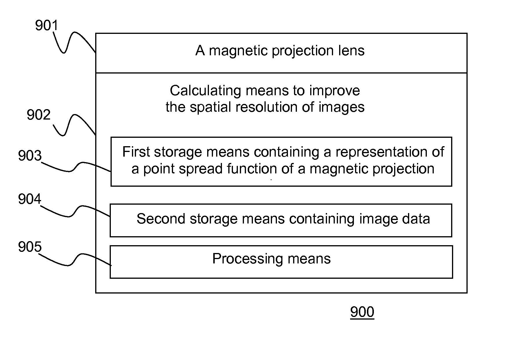
[0063]A block diagram of an imaging apparatus according to this invention required to produce high spatial resolution images is shown in FIG. 9. The imaging apparatus 900, comprises: a magnetic projection lens 901; a calculating means to improve the spatial resolution of images 902; whereby images collected from said magnetic projection lens can be presented with a higher spatial resolution.
[0064]The calculating means to improve spatial resolution of images 902 comprises: a first storage means containing a representation of the point spread function of said magnetic projection lens 903; a second storage means containing image data 904; and a processing means 905, whereby said point spread function is deconvolved from said image data.
[0065]As will be appreciated by those ordinarily skilled in the art, modifications, and additions can be made to the apparatus shown in FIG. 9.
second embodiment
[0066]A block diagram of a photoelectron microscope according to this invention required to produce high spatial resolution photoelectron images is shown in FIG. 10. The photoelectron microscope 1000, comprises: a photoelectron imager with a magnetic projection lens 1001; a calculating means to improve the spatial resolution of images 1002; whereby images collected from said photoelectron imager with a magnetic projection lens 1001 can be presented with a higher spatial resolution.
[0067]The calculating means to improve spatial resolution of images 1002 comprises: a first storage means containing a representation of the point spread function of said photoelectron imager with a magnetic projection lens 1003; a second storage means containing image data 1004; and a processing means 1005, whereby said point spread function is deconvolved from said image data.
[0068]As will be appreciated by those ordinarily skilled in the art, modifications, and additions can be made to the apparatus sho...
third embodiment
[0069]A block diagram of a photoelectron microscope according to this invention required to produce high spatial resolution photoelectron images is shown in FIG. 11. The photoelectron microscope 1100, comprises: a photoelectron imager with a magnetic projection lens and CORF 1101; a calculating means to improve the spatial resolution of images 1102; whereby images collected from said photoelectron imager with a magnetic projection lens and CORF 1101 can be presented with a higher spatial resolution.
[0070]The calculating means to improve spatial resolution of images 1102 comprises: a first storage means containing a representation of the point spread function of a magnetic projection lens and CORF 1103; a second storage means containing the image data 1104; and a processing means 1105, whereby said point spread function is deconvolved from said image data.
[0071]As will be appreciated by those ordinarily skilled in the art, modifications, and additions can be made to the apparatus sho...
PUM
| Property | Measurement | Unit |
|---|---|---|
| photoelectron microscope | aaaaa | aaaaa |
| photoelectron imager | aaaaa | aaaaa |
| Photoelectron microscopes | aaaaa | aaaaa |
Abstract
Description
Claims
Application Information
 - R&D
- Intellectual Property
- Life Sciences
- Materials
- Tech Scout
- Unparalleled Data Quality
- Higher Quality Content
- 60% Fewer Hallucinations
Browse by: Latest US Patents, China's latest patents, Technical Efficacy Thesaurus, Application Domain, Technology Topic, Popular Technical Reports.
© 2025 PatSnap. All rights reserved.Legal|Privacy policy|Modern Slavery Act Transparency Statement|Sitemap|About US| Contact US: help@patsnap.com