
Flat panel display module having speaker function

a technology of display module and speaker, which is applied in the direction of transducer diaphragm, electrical apparatus casing/cabinet/drawer, instruments, etc., can solve the problems of display not being suitable as a display for a mobile device which requires a reduction in thickness and size, and achieves simple structure, clear sound, and reduced size and thickness

Active Publication Date: 2009-07-28
CASIO COMPUTER CO LTD
View PDF64 Cites 72 Cited by
  • Summary
  • Abstract
  • Description
  • Claims
  • Application Information

AI Technical Summary

Benefits of technology

This design enables a compact and cost-effective flat panel display module with clear sound output, suitable for mobile devices, by eliminating the need for additional sound leading path components and preventing display failure through effective vibration management.

Problems solved by technology

When the speaker is aligned with the picture display on the front surface of the device in this manner, a front area of the entire device is increased, this increase is against a demand for a reduction in size, and this display is not suitable as a display for a mobile device which requires a reduction in thickness and size.

Method used


Image

  • Flat panel display module having speaker function
  • Flat panel display module having speaker function
  • Flat panel display module having speaker function

Examples


first embodiment

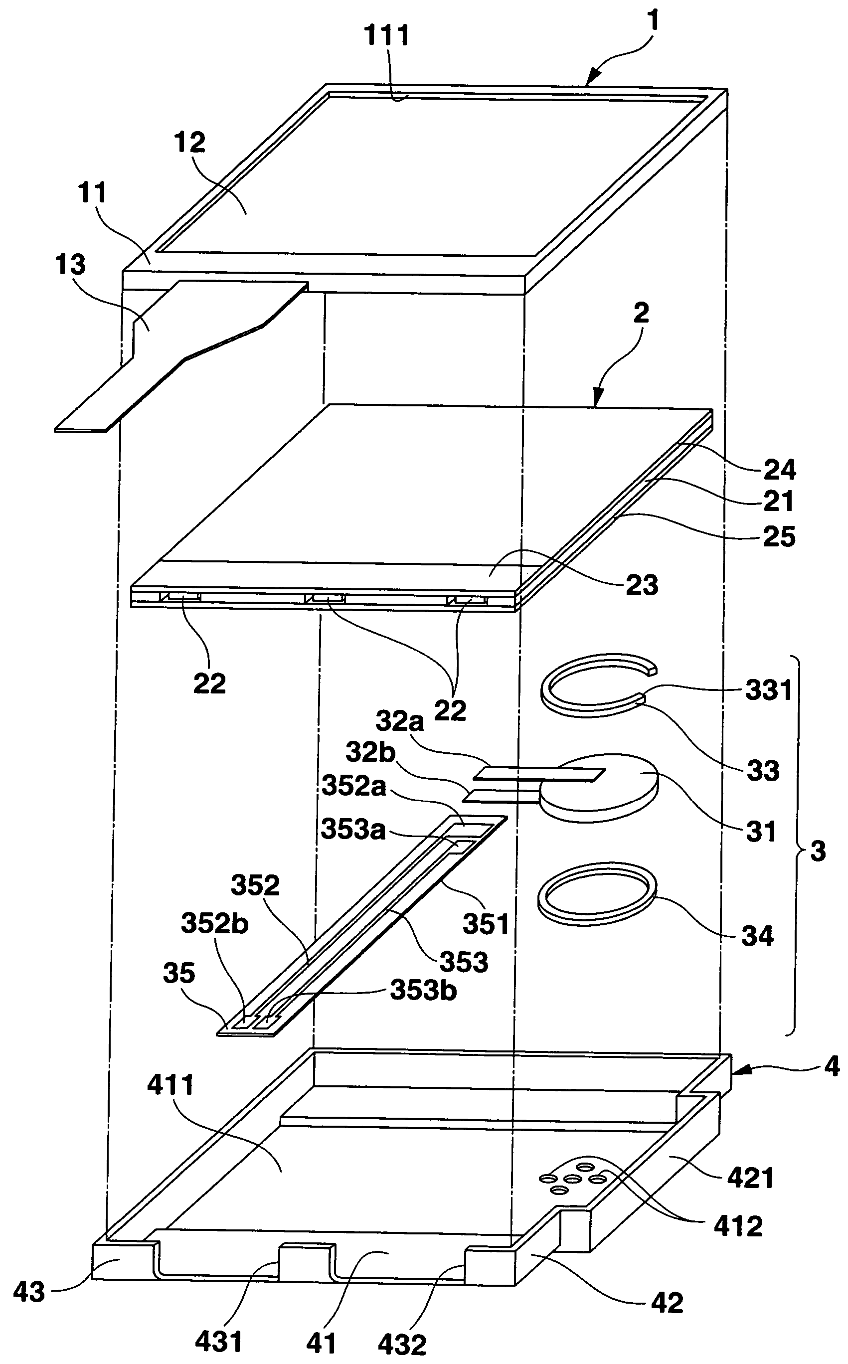
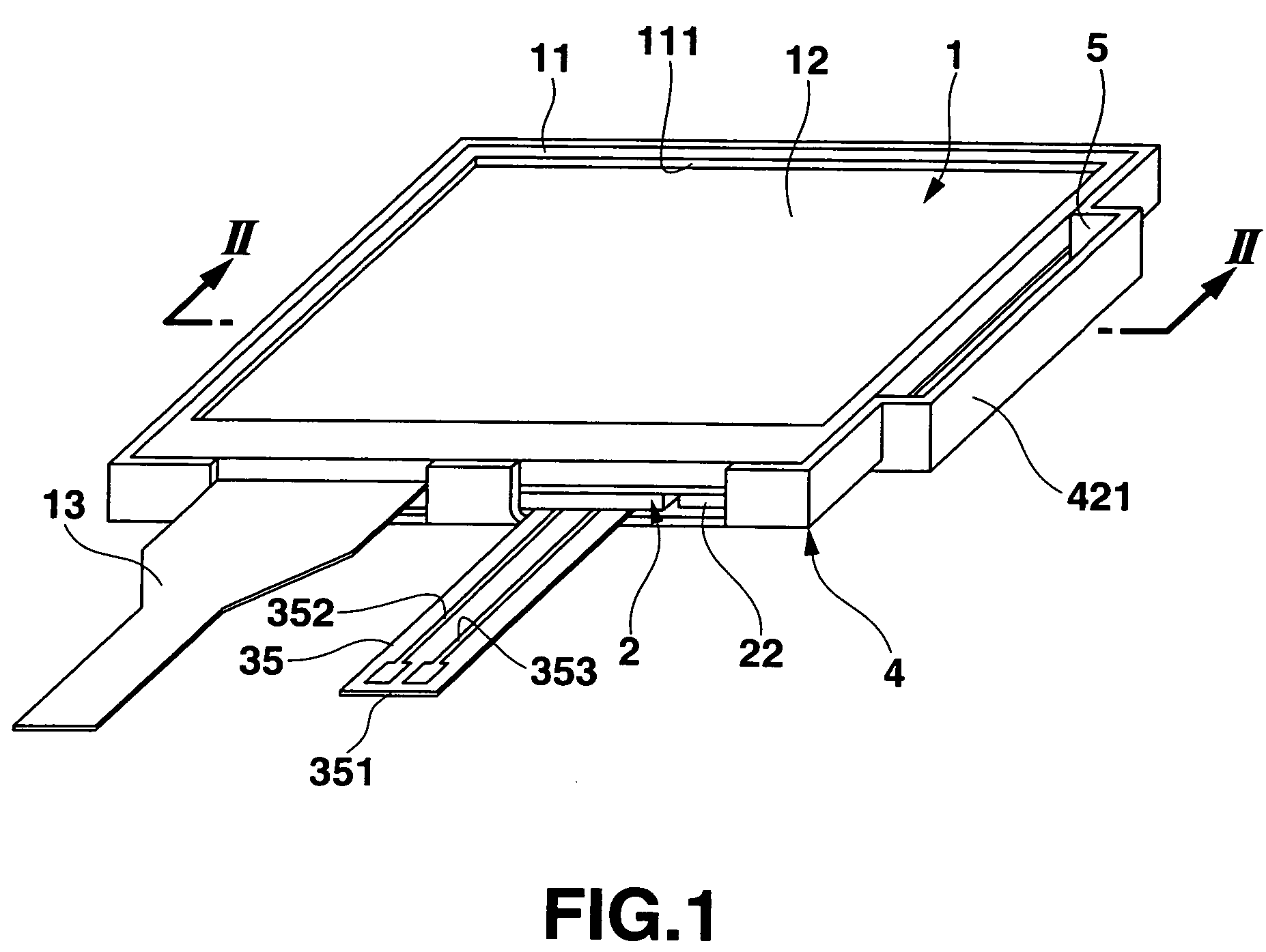
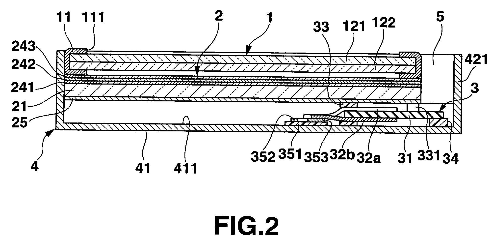
[0047]FIG. 1 is a perspective view showing a liquid crystal display module as a first embodiment according to the present invention, FIG. 2 is a cross-sectional view taken along a line II-II in FIG. 1, and FIG. 3 is an exploded perspective view of the display module.

[0048]As shown in FIG. 3, a liquid crystal display module according to this embodiment is mainly constituted of a liquid crystal display unit 1, a backlight unit 2, a sound source unit 3 and an external case 4. The liquid crystal display unit 1 is formed of a panel case 11 and a liquid crystal display panel 12 accommodated in the panel case 11. As shown in FIG. 2, the liquid crystal display panel 12 is constituted by bonding a pair of rectangular glass substrates 121 and 122 respectively having non-illustrated electrodes formed on the opposite surface thereof with a predetermined gap interposed therebetween by using a non-illustrated frame-like sealing member in such a manner that the opposite surfaces face each other an...

second embodiment

[0066]the present invention will now be described with reference to FIGS. 4 and 5. It is to be noted that like reference numerals denote constituent elements equal to those in the foregoing embodiment, thereby omitting a description thereof.

[0067]As shown in FIG. 4, a liquid crystal display module according to this embodiment is a stereophonic sound type liquid crystal display module provided with a pair of sound source units 3 and 6. That is, the sound source unit 3 provided in the liquid crystal display module according to the foregoing embodiment and the sound source unit 6 having substantially the same structure are symmetrically arranged in relation to a central line which divides a longitudinal direction (a screen lateral direction) of a display surface of the liquid crystal display module into two.

[0068]In this case, a piezoelectric ceramic plate 61 having a pair of electrodes 62a and 62b which have the same structure being electrically conductive and attached thereon, a C-sh...


PUM


Abstract

An image display module include a flat panel display, a sound source element disposed on a rear surface side opposite to a display observation side of the panel display, and a sound leading path through which a sound wave generated from the sound source element is led to the display observation side.

Description

CROSS-REFERENCE TO RELATED APPLICATIONS[0001]This application is based upon and claims the benefit of priority from prior Japanese Patent Application No. 2005-279802, filed Sep. 27, 2005, the entire contents of which are incorporated herein by reference.BACKGROUND OF THE INVENTION[0002]1. Field of the Invention[0003]The present invention relates to a flat panel display module having a speaker function.[0004]2. Description of the Related Art[0005]In recent years, as a display for a mobile device such as a mobile phone, a flat panel display (which will be referred to as an FPD hereinafter) such as a liquid crystal display or an organic electroluminescent (EL) display suitable for a reduction in size and thickness has been often used.[0006]A mobile phone has been advancing from a simple telephone to a composite device provided with functions as a television or a personal digital assistant (PDA), and a display used in such a mobile device is demanded to not only display a picture or ima...

Claims


Application Information

Patent Timeline
Patent Type & Authority Patents(United States)
IPC IPC(8): A47B81/06
CPCG06F1/1605H04R5/02H04R1/323H04N5/64G02F1/1333H04R17/00G06F1/00
Inventor TOJO, MAKOTO
Owner CASIO COMPUTER CO LTD
Learn More