Magnetoresistive device, thin film magnetic head, head gimbal assembly and magnetic disk unit exhibiting superior magnetoresistive effect

a magnetoresistive device and thin film technology, applied in the field of magnetoresistive devices, thin film magnetic heads, head gimbal assemblies and magnetic disk units exhibiting superior magnetoresistive effects, can solve the problem achieve the effect of reducing the amount of resistance change due to the second magnetization fixed film, increasing the amount of resistance change, and preventing the loss of resistance chang

Active Publication Date: 2009-07-21
TDK CORPARATION
View PDF15 Cites 0 Cited by
  • Summary
  • Abstract
  • Description
  • Claims
  • Application Information

AI Technical Summary

Benefits of technology

[0012]In the magnetoresistive device, the thin film magnetic head, the head gimbal assembly and the magnetic disk unit according to the first aspect of the invention, the second magnetization fixed film farther from the magnetization free layer out of the first magnetization fixed film and the second magnetization fixed film has a bulk scattering coefficient of 0.25 or less, so a bulk scattering effect by the second magnetization fixed film which has a function of canceling out the amount of resistance change between the magnetization free layer and the first magnetization fixed film can be prevented.
[0015]In the magnetoresistive device, the thin film magnetic head, the head gimbal assembly and the magnetic disk unit according to the second aspect of the invention, the second magnetization fixed film farther from the magnetization free layer out of the first magnetization fixed film and the second magnetization fixed film includes at least one selected from the group consisting of tantalum (Ta), chromium (Cr) and vanadium (V), so a bulk scattering effect by the second magnetization fixed film which has a function of canceling out the amount of resistance change between the magnetization free layer and the first magnetization fixed film can be prevented.
[0019]The magnetoresistive device, the thin film magnetic head, the head gimbal assembly and the magnetic disk unit according to the first aspect of the invention comprises: a first magnetization fixed layer including a first magnetization fixed film having a magnetization direction fixed in a predetermined direction and a second magnetization fixed film being antiferromagnetically coupled to the first magnetization fixed film and having a bulk scattering coefficient of 0.25 or less; the magnetization free layer being disposed on a side of the first magnetization fixed film opposite to a side where the second magnetization fixed film is disposed and having a magnetization direction changing depending upon an external magnetic field; and the current path for flowing a sense current through the first magnetization fixed layer and the magnetization free layer in a direction perpendicular to a laminate surface, so a reduction in the amount of resistance change due to the second magnetization fixed film can be prevented. Therefore, a magnetoresistive ratio can be improved through increasing the amount of resistance change as a whole, and they can respond to a higher recording density. In particular, when the second magnetization fixed film has a bulk scattering coefficient of 0.20 or less, a larger amount of resistance change can be obtained, and they can respond to a further higher recording density.
[0020]The magnetoresistive device, the thin film magnetic head, the head gimbal assembly, the magnetic disk unit and a wafer according to the second aspect of the invention comprises: a first magnetization fixed layer including a first magnetization fixed film having a magnetization direction fixed in a predetermined direction, and a second magnetization fixed film being antiferromagnetically coupled to the first magnetization fixed film and including at least one selected from the group consisting of tantalum (Ta), chromium (Cr) and vanadium (V); a magnetization free layer being disposed on a side of the first magnetization fixed film opposite to a side where the second magnetization fixed film is disposed and having a magnetization direction changing depending upon to an external magnetic field; and the current path for flowing a sense current through the first magnetization fixed layer and the magnetization free layer in a direction perpendicular to a laminate surface, so a reduction in the amount of resistance change due to the second magnetization fixed film can be prevented. Therefore, a magnetoresistive ratio can be improved through increasing the amount of resistance change as a whole, and they can respond to a higher recording density.

Problems solved by technology

On the other hand, a current flows through the SV film in a laminate direction, so there is a problem that a part of the amount of resistance change is lost due to the structural characteristics.

Method used


Image

  • Magnetoresistive device, thin film magnetic head, head gimbal assembly and magnetic disk unit exhibiting superior magnetoresistive effect
  • Magnetoresistive device, thin film magnetic head, head gimbal assembly and magnetic disk unit exhibiting superior magnetoresistive effect
  • Magnetoresistive device, thin film magnetic head, head gimbal assembly and magnetic disk unit exhibiting superior magnetoresistive effect

Examples


example 1

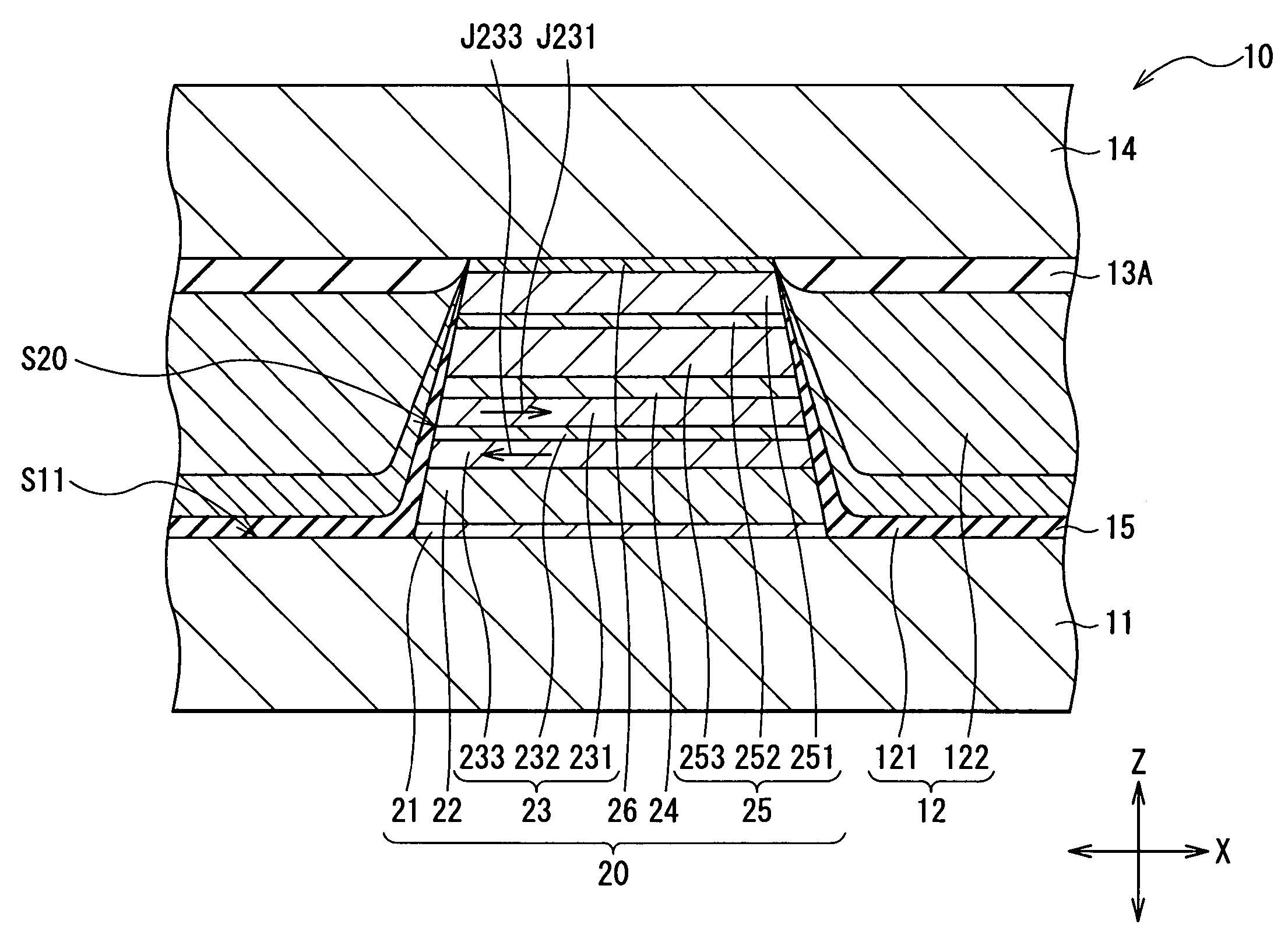
[0093]In the example, samples in the case of X=Ta, that is, in the case where the second magnetization fixed film 233 (“AP2”) was made of a cobalt iron tantalum alloy (CoFeTa) were examined. Four different tantalum contents: 0.8 at %, 1.0 at %, 5.0 at % and 10.0 at % of the second magnetization fixed film 233 were prepared. The results are shown in Table 1.

[0094]

TABLE 1TaCONTENTRAA Δ RMR RATIO[at %][Ωμm2][mΩμm2][%]β0.80.1021.731.700.301.00.1132.031.800.235.00.1282.592.030.0910.00.1423.052.150.08

example 2

[0095]In the example, samples in the case of X=Cr or X=V, that is, in the case where the second magnetization fixed film 233 (“AP2”) was made of a cobalt iron chromium alloy (CoFeCr) or a cobalt iron vanadium alloy (CoFeV) were examined. Four different chromium contents and four different vanadium contents: 11 at %, 13 at %, 16 at % and 19 at % of the second magnetization fixed film 233 were prepared. The results are shown in Table 2.

[0096]

TABLE 2Cr, VCONTENTRAA Δ RMR RATIO[at %][Ωμm2][mΩμm2][%]βCr; 110.1201.821.520.34V; 110.1301.891.450.30Cr; 130.1312.191.670.25V; 130.1412.331.650.21Cr; 160.1422.561.800.23V; 160.1572.721.730.18Cr; 190.1502.601.730.20V; 190.1632.791.710.16

example 3

[0101]The detailed structure of each sample subjected to the auxiliary experiment is shown below.

Ta1 / NiFeCr5 / IrMn7 / CoFeX5 / Cu3 / CoFe2 / Cap

The number attached to the material of each layer indicate the thickness (nm) of each layer. More specifically, “Ta / NiFeCr”, “IrMn”, “CoFeX”, “Cu”, “CoFe” and “Cap” correspond to the base layer 21, the antiferromagnetic layer 22, the magnetization fixed layer 23, the intermediate layer 24, the magnetization free layer 25 and the cap layer 26, respectively. Herein, X is an added material which is one kind selected from the group consisting of Ta, Cr and V. Four contents of each added material in the magnetization fixed film (CoFeX5) were prepared. The measured amounts of resistance change AΔR are shown in Table 4.

[0102]

TABLE 4TaCON-CrVTENTA Δ RCONTENTA Δ RCONTENTA Δ R[at %][mΩμm2][at %][mΩμm2][at %][mΩμm2]0.80.9792111.0158110.91881.00.8467130.8505130.77115.00.6146160.8170160.725910.00.5990190.7686190.6966


PUM

PropertyMeasurementUnit
thicknessaaaaaaaaaa
thicknessaaaaaaaaaa
thicknessaaaaaaaaaa

Abstract

Provided are a magnetoresistive device capable of obtaining a larger amount of resistance change and responding to a higher recording density and a thin film magnetic head comprising the magnetoresistive device. A first magnetization fixed film and a second magnetization fixed film have magnetization directions antiparallel to each other, and the second magnetization fixed film farther from a magnetization free layer is made of, for example, a material including at least one selected from the group consisting of tantalum (Ta), chromium (Cr) and vanadium (V), and has a bulk scattering coefficient of 0.25 or less. Thereby, a bulk scattering effect by the second magnetization fixed film which has a function of canceling out the amount of resistance change between the magnetization free layer and the first magnetization fixed film can be prevented, and a magnetoresistive ratio ΔR / R can be improved, and recorded magnetic information with a higher recording density can be read out.

Description

BACKGROUND OF THE INVENTION[0001]1. Field of the Invention[0002]The present invention relates to a magnetoresistive device exhibiting a giant magnetoresistive effect, a thin film magnetic head, a head gimbal assembly and a magnetic disk unit comprising the magnetoresistive device, and more specifically the invention related to a magnetoresistive device in which a current flows in a laminate direction during use, and a thin film magnetic head, a head gimbal assembly and a magnetic disk unit comprising the magnetoresistive device.[0003]2. Description of the Related Art[0004]Conventionally, thin film magnetic heads comprising a MR device which exhibits a magnetoresistive effect (MR) are broadly used to reproduce information on magnetic recording media such as hard disks. In recent years, as the recording densities of the magnetic recording media increase, thin film magnetic heads using a giant magnetoresistive device (GMR device) which exhibits a giant magnetoresistive effect (GMR) are...

Claims


Application Information

Patent Timeline
Patent Type & Authority Patents(United States)
IPC IPC(8): G11B5/33G11B5/127G11B5/39
CPCB82Y10/00G11B5/3929B82Y25/00G11B2005/3996
Inventor MIYAUCHI, DAISUKEMIZUNO, TOMOHITO
Owner TDK CORPARATION
Why Eureka
Try Eureka